Riser assembly and bottom M.2 cabled adapter cable routing
See this section to learn how to do cable routing for riser assembly and bottom M.2 cabled adapter.
Proceed to the section corresponding to the selected configuration on the left wing of riser assembly:
PCIe assembly configuration
Riser assembly to system board
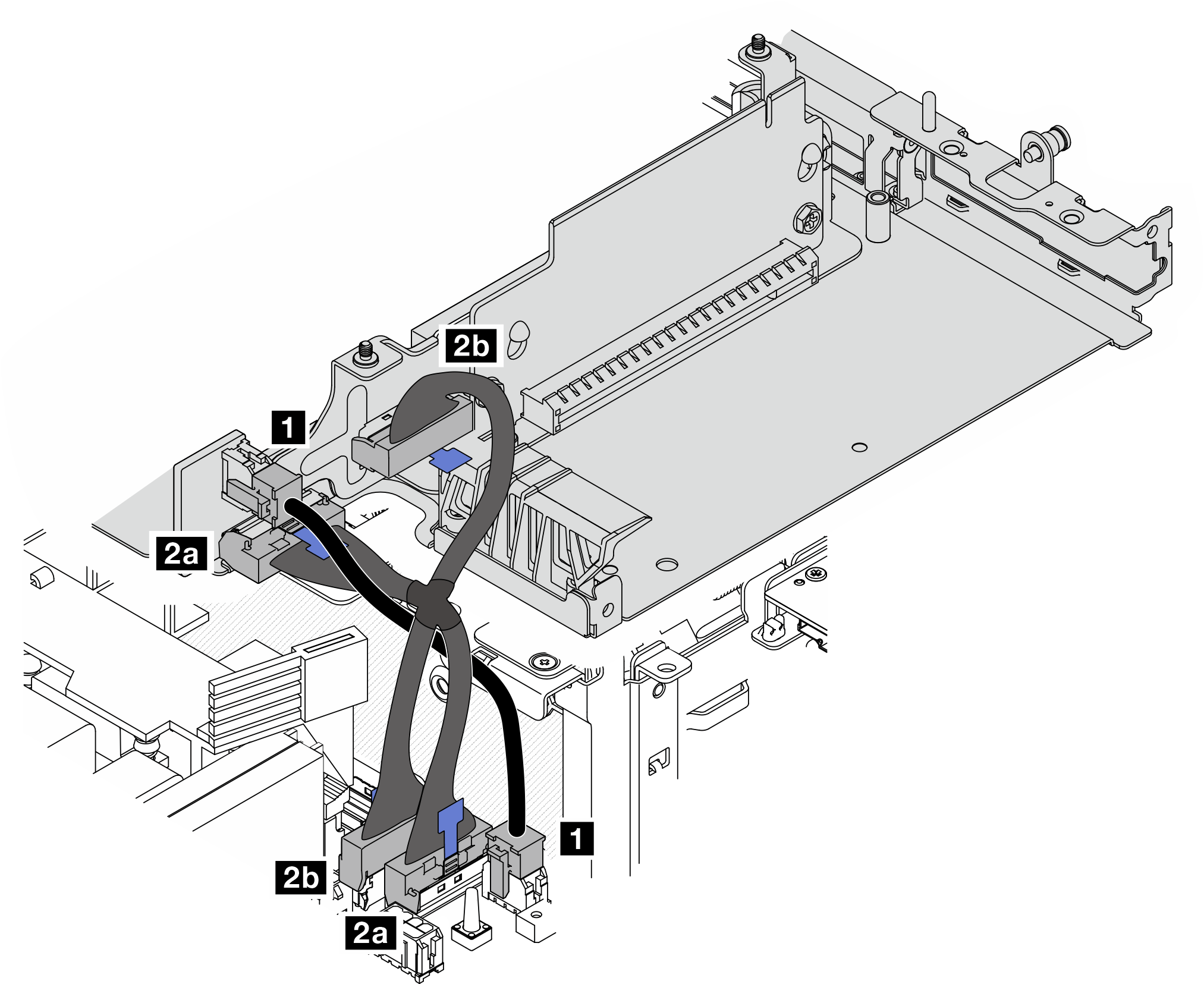 | |||
| Cable | From: PCIe cabled riser card | To: System board | Cable length |
| 1 | Power connector | M.2 cabled adapter / PCIe cabled riser card power connector | 100mm |
| 2 | 2a MCIO 1 connector 2b MCIO 2 connector | 2a MCIO 1 connector 2b MCIO 2 connector | 140/120mm |
System board to bottom M.2 cabled adapter
| Top side of the node | |||
 | |||
| Bottom side of the node | |||
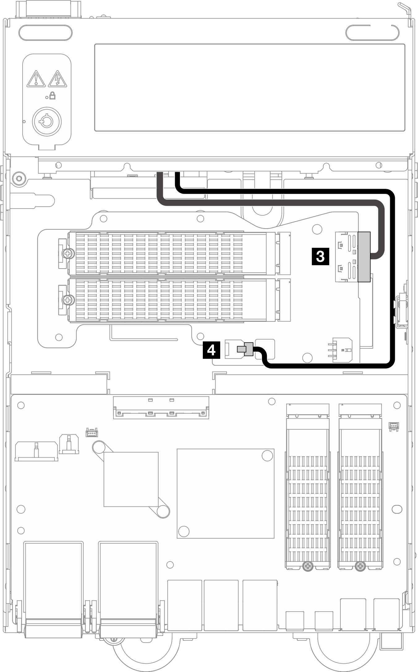 | |||
| Cable | From: System board | To: Bottom M.2 cabled adapter | Cable length |
| 3 | PCIe Gen 3 / SATA connector | MCIO 1 connector | 200mm |
| 4 | M.2 cabled adapter power connector | Power connector 1 | 350mm |
7mm drive backplane configuration
| Top side of the node | |||
 | |||
| Bottom side of the node | |||
 | |||
| Cable | From | To | Cable length |
| 1 | 1a Backpalne 1: NVMe 1 connector 1b Backplane 2: NVMe 0 connector | 1 System board: PCIe Gen 4 MCIO 1 connector | 130/175mm |
| 2 | Backpalne 1: SATA connector | System board: PCIe Gen 3 / SATA connector | 150mm |
| 3 | Backpalne 1: Backplane power connector | I/O module board: Backplane power connector | 300mm |
| 4 | System board: M.2 cabled adapter power connector | Bottom M.2 cabled adapter: Power connector 1 | 350mm |
| 5 | System board: PCIe Gen 4 MCIO 2 connector | Bottom M.2 cabled adapter: MCIO 1 connector | 220mm |
M.2 assembly configuration
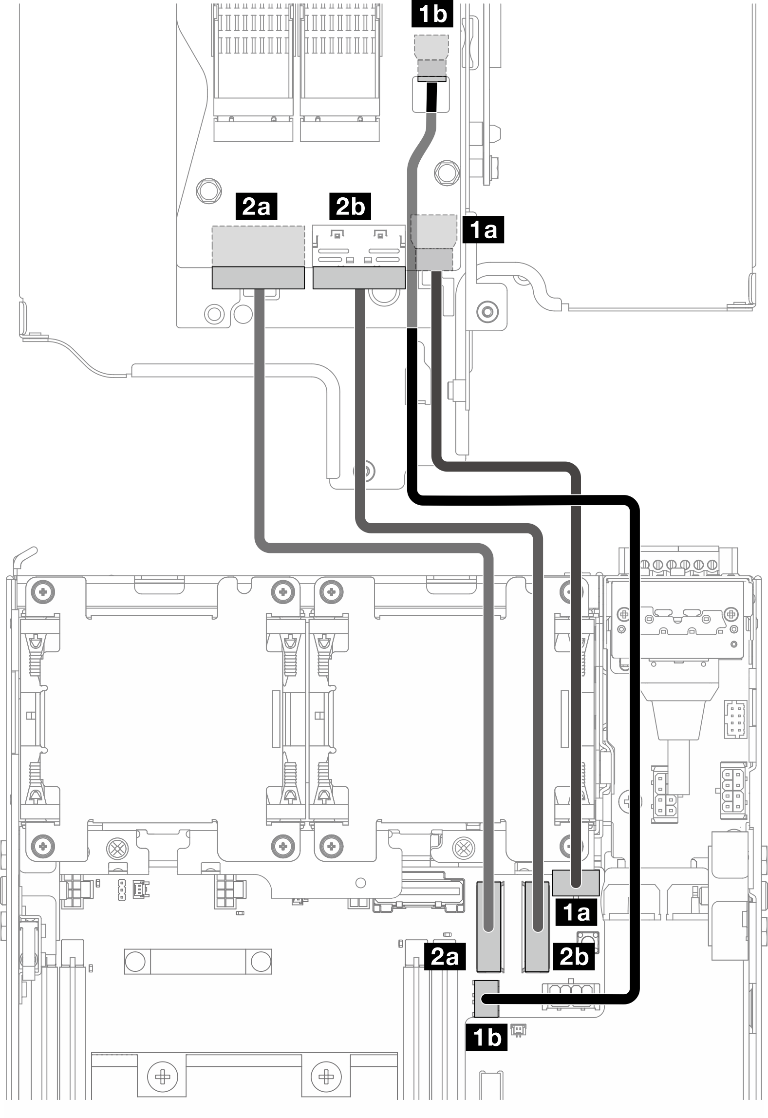
| Cable | From: M.2 cabled adapter | To: System board | Cable length |
| 1 | 1a Power connector 1 1b Power connector 2 | 1a M.2 cabled adapter / PCIe cabled riser card power connector 1b M.2 cabled adapter power connector | 170/200mm |
| 2 | 2a MCIO 1 connector 2b MCIO 2 connector | 2a PCIe Gen 4 MCIO 1 connector 2b PCIe Gen 4 MCIO 2 connector | 150mm |