System-board switches

Use this information to locate and define system-board switches in the blade server.

The following illustration shows the locations of the two switch blocks (SW2 and SW3) and the light path diagnostics switch on the system board.
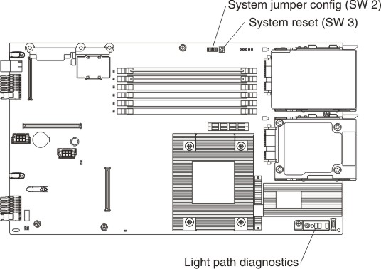
Graphic illustrating system-board switches

The following table describes the function of each switch in the switch blocks (SW2, SW3).

SwitchDescription
SW2Switch block 2 has the following switches:
  • 1 - Boot block
  • 2 - Force power on
  • 3 - Wake On LAN disable
    • On: Disabled
    • Off: Enabled (default)
  • 4 - Wake On LAN bypass disable
    • On: Disabled
    • Off: Enabled (default)
  • 5 - Debug serial port
    • On: Disabled
    • Off: Enabled (default)
  • 6 - RCTRST (I/O controller hub (ICH) real-time clock (RTC))
    • On: Reset RTC
    • Off: Normal (default)
  • 7 - Force PCIX 100
    • On: Force PCIX frequency at 100MHz maximum
    • Off: PCIX frequency at 133 MHz maximum (default)
  • 8 - Bypass power-on password during next server start
    • On: Enabled
    • Off: Disabled (default)
SW3Switch block 3 is a system-reset switch