System-board jumpers
Use this information to locate the system-board jumpers.
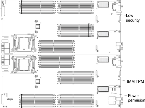
The following illustration shows the locations of the jumpers on the system board.
The following table describes the function of each jumper on the system board.
Two column table.
| Jumper number | Description |
|---|---|
| IMM TPM (JP2461) | Two-pin jumper. The default is no jumper. Place a jumper on pins 1 and 2 to indicate a physical presence to the IMM2 TPM chip. |
| Low Security (J2101) | Three-pin jumper block. The default position is pins 2 and 3. |
| Power permission (JP9601) | Two-pin jumper block. The default is no jumper. Place a jumper on pins 1 and 2 to force power permission from the IMM2 to the real time management module (RTMM). |
Give documentation feedback