Vertical mounting kit installation guide
About this task
Note
- The left and right mounting glides are part of the fire enclosure. Therefore, ensure the glides are installed before attempting to mount the server in vertical orientation.
- Two people are required for this task.
Procedure
- Remove the two screws that secure the lower portion of SR670 rack mounting brackets on both sides, and dispose the screws.Figure 1. Removing screws from the rack mounting brackets
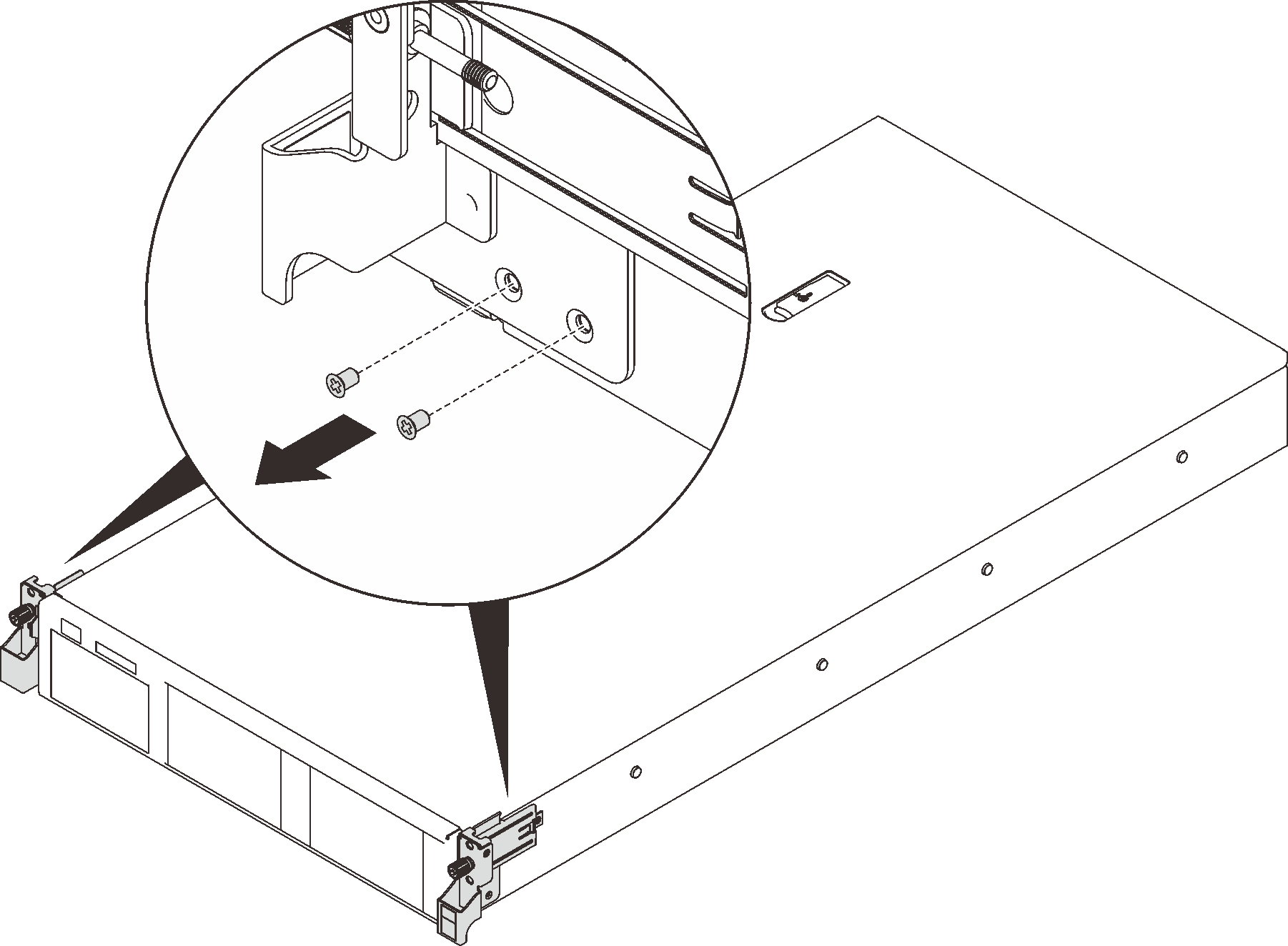 NoteDo not fully remove the rack mounting brackets as they are required to secure the server into the vertical rack.
 - Secure the mounting glides to the server.Figure 2. Securing the mounting glides
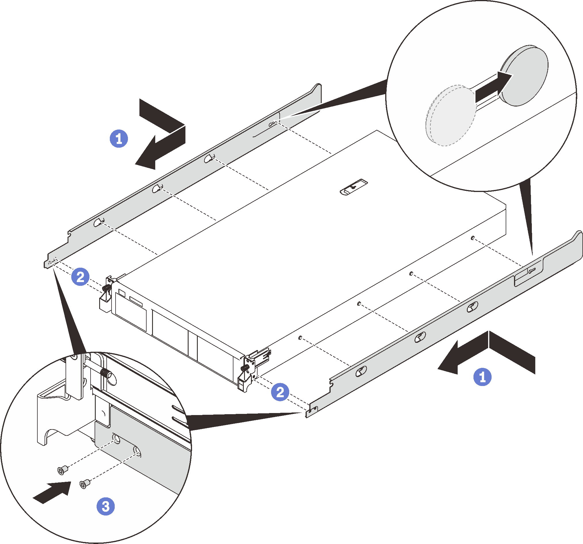
- ① Align the key hole slots in the glides to the T-head pins on both sides of the server, and slide the mounting glides forward until the pins are secured in the slots.
- ② Align the two holes on the mounting glide to the threaded standoffs on the front end of the server.
- ③ Secure each mounting glide with two of the M3.5 x 5 mm screws with pre-applied adhesive that come with the vertical mounting kit.
- Install one C-channel in the lower portion of the rack cabinet.Figure 3. Installing the lower C-channel
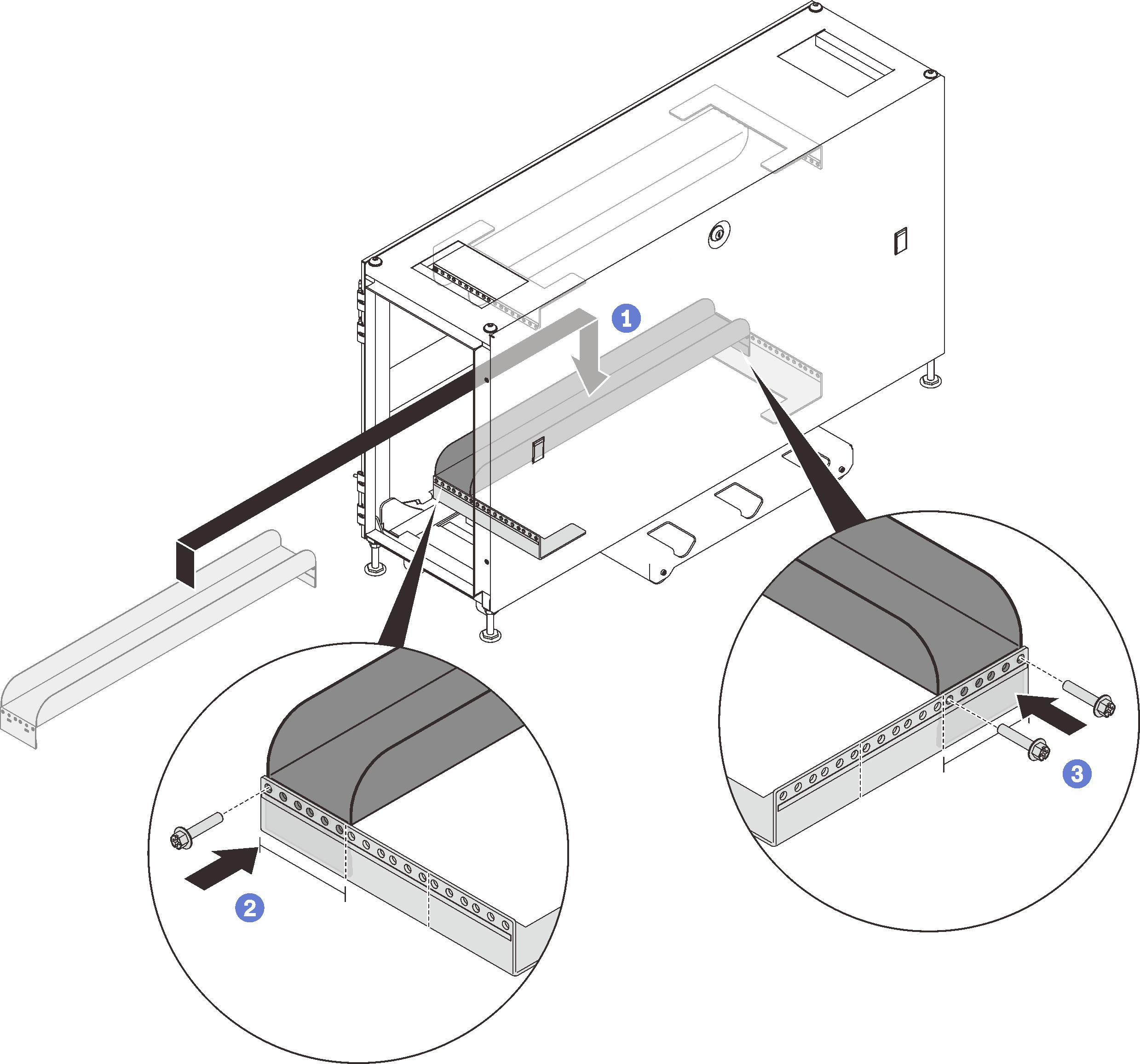
- ① Align the C-channel between the lower rack EIA flanges.
- ② Secure the front end of the C-channel to the front EIA flange with one M5 x 20 mm screw through the left most hole in the channel.
- ③ Secure the rear end of the C-channel to the rear EIA flange with two M5 x 20 mm screws through the right and left most holes in the bracket.
AttentionDo NOT over-tighten the screws as the rack EIA flange could be deformed. - Install the other C-channel in the upper portion of the rack cabinet.Figure 4. Installing the upper C-channel
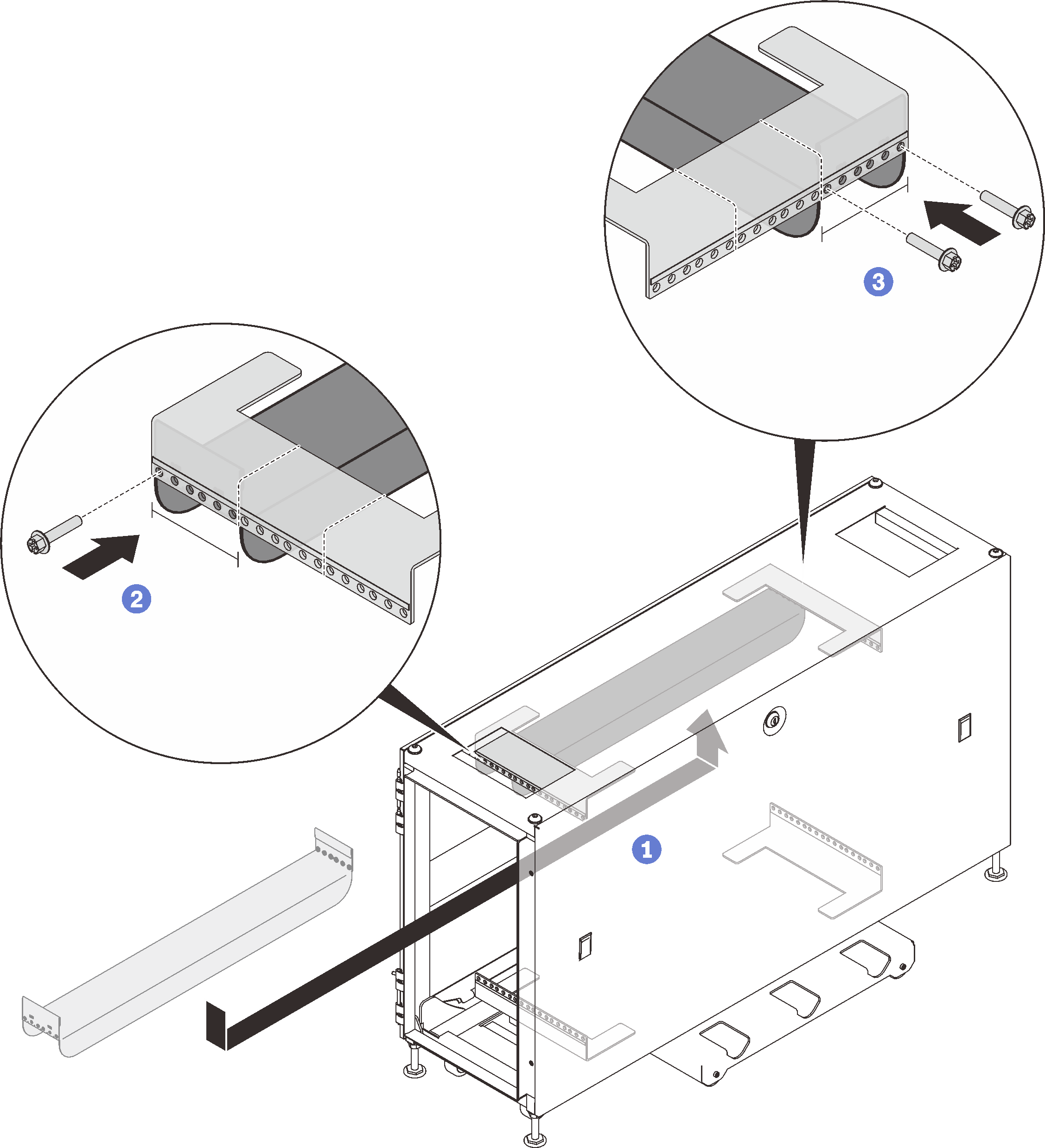
- ① Have one person hold and align the C-channel between the upper rack EIA flanges.
- ② Secure the front end of the C-channel to the front EIA flange with one M5 x 20 mm screw through the left most hole in the channel.
- ③ Secure the rear end of the C-channel to the rear EIA flange with two M5 x 20 mm screws through the right and left most holes in the bracket.
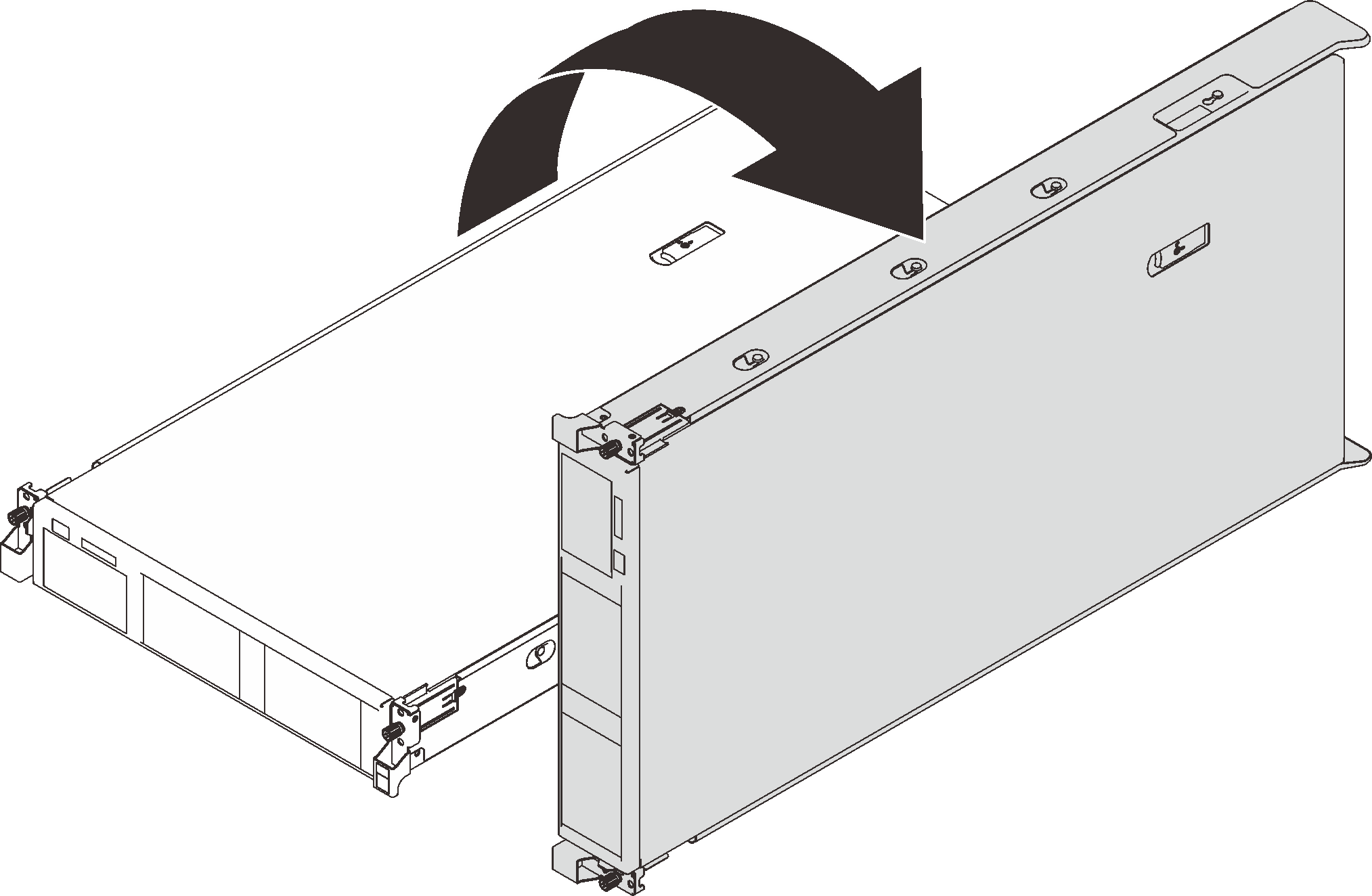
- Rotate the server 90 degree clockwise so that the right side is facing down.Figure 5. Rotating the server
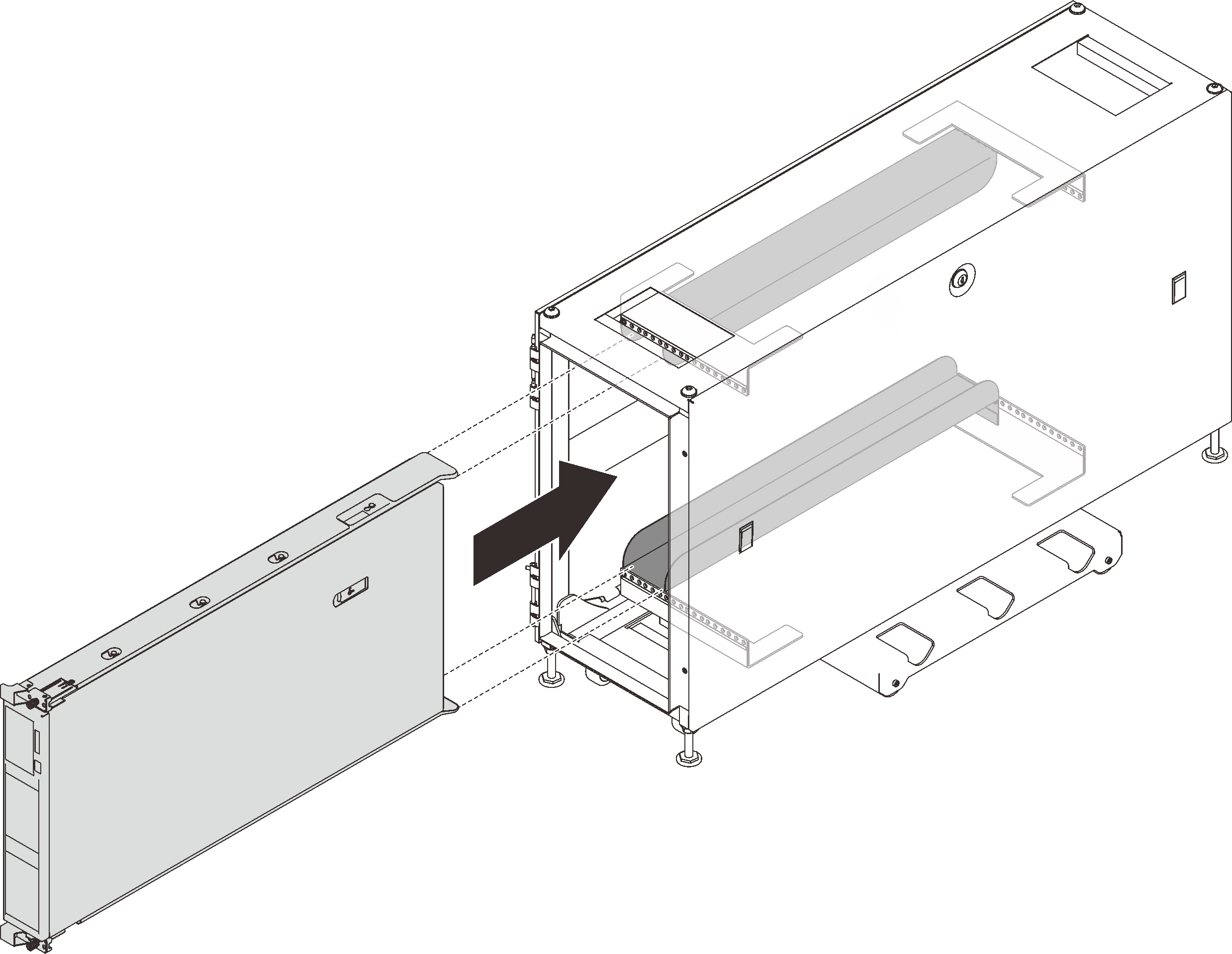
- Lift the server with two people, and slide it into the C-channels.Figure 6. Installing the server into the rack cabinet
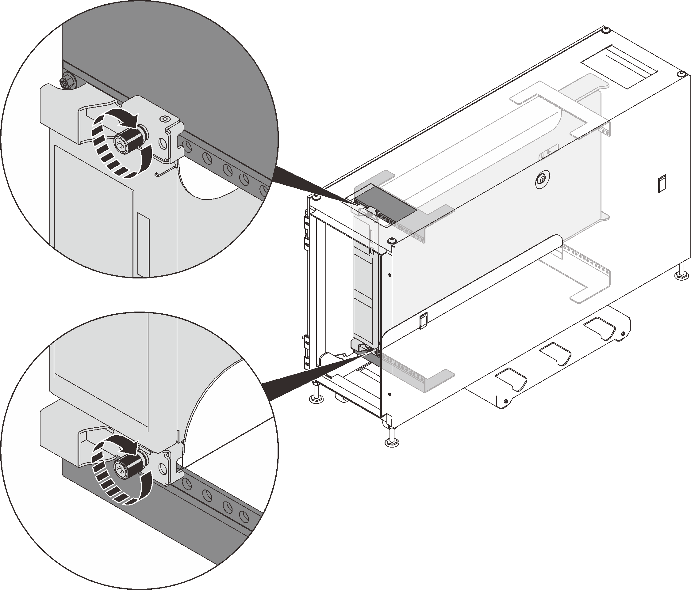
- Tighten both the upper and lower captive thumb screws.Figure 7. Securing the rack mounting brackets
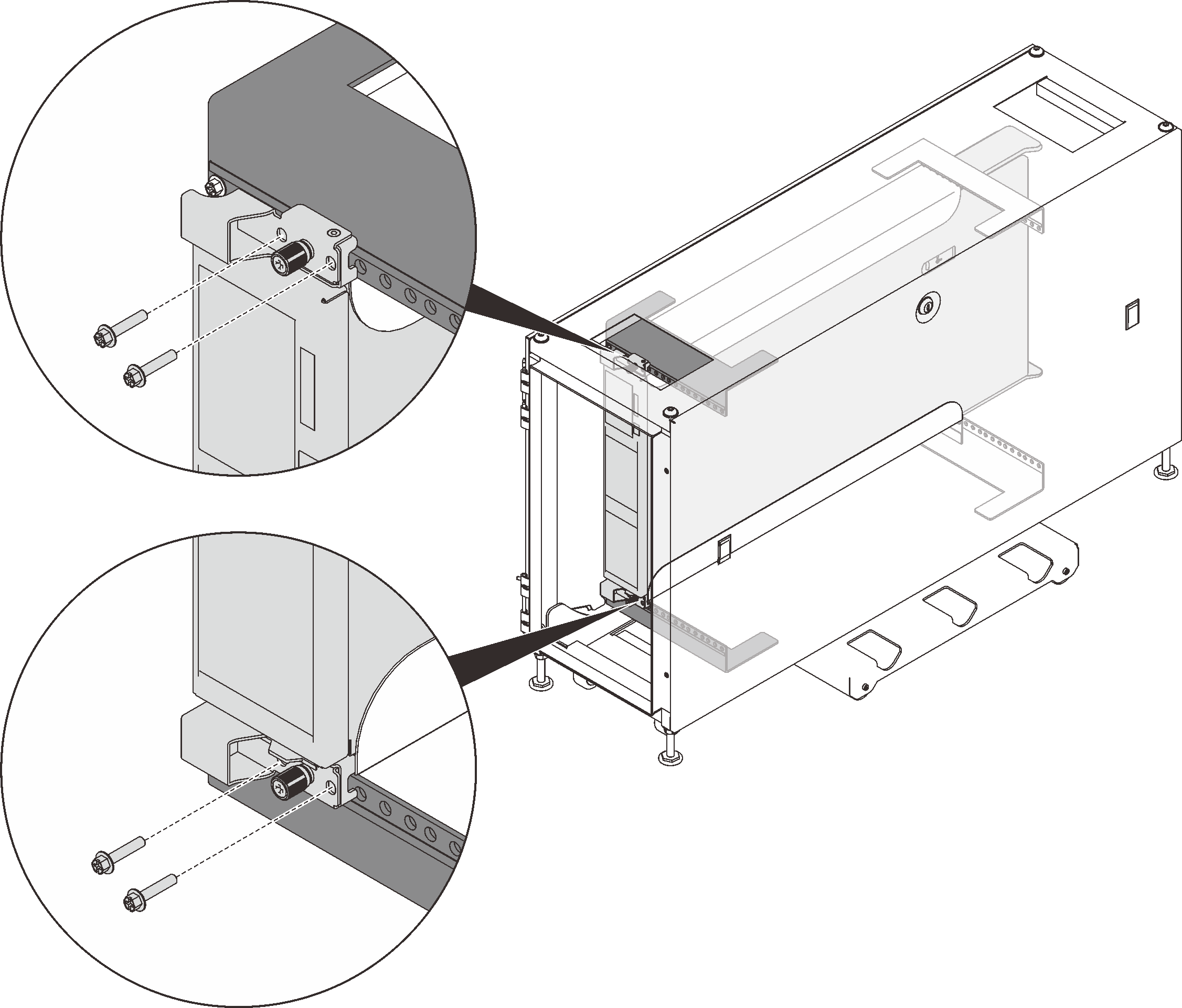
- Secure each rack mounting bracket with two M5 x 20 mm screws.Figure 8. Securing the rack mounting brackets
Give documentation feedback