Parts list
Identify each of the components that is available for your server with the parts list.
For more information about ordering parts:
Go to Lenovo Data Center Support and navigate to the support page for your node or chassis.
Click .
Enter the serial number to view a listing of parts for your system.
It is highly recommended that you check the power summary data for your server using Lenovo Capacity Planner before purchasing any new parts.
Note
Depending on the model, your server components might look slightly different from the illustration.
The parts listed in the following tables are identified as one of the following:
- T1: Tier 1 customer replaceable unit (CRU). Replacement of Tier 1 CRUs is your responsibility. If Lenovo installs a Tier 1 CRU at your request with no service agreement, you will be charged for the installation.
- T2: Tier 2 customer replaceable unit (CRU). You may install a Tier 2 CRU yourself or request Lenovo to install it, at no additional charge, under the type of warranty service that is designated for your server.
- F: Field replaceable unit (FRU). FRUs must be installed only by trained service technicians.
- C: Consumable and Structural parts. Purchase and replacement of consumable and structural parts is your responsibility. If Lenovo acquires or installs a structural component at your request, you will be charged for the service.
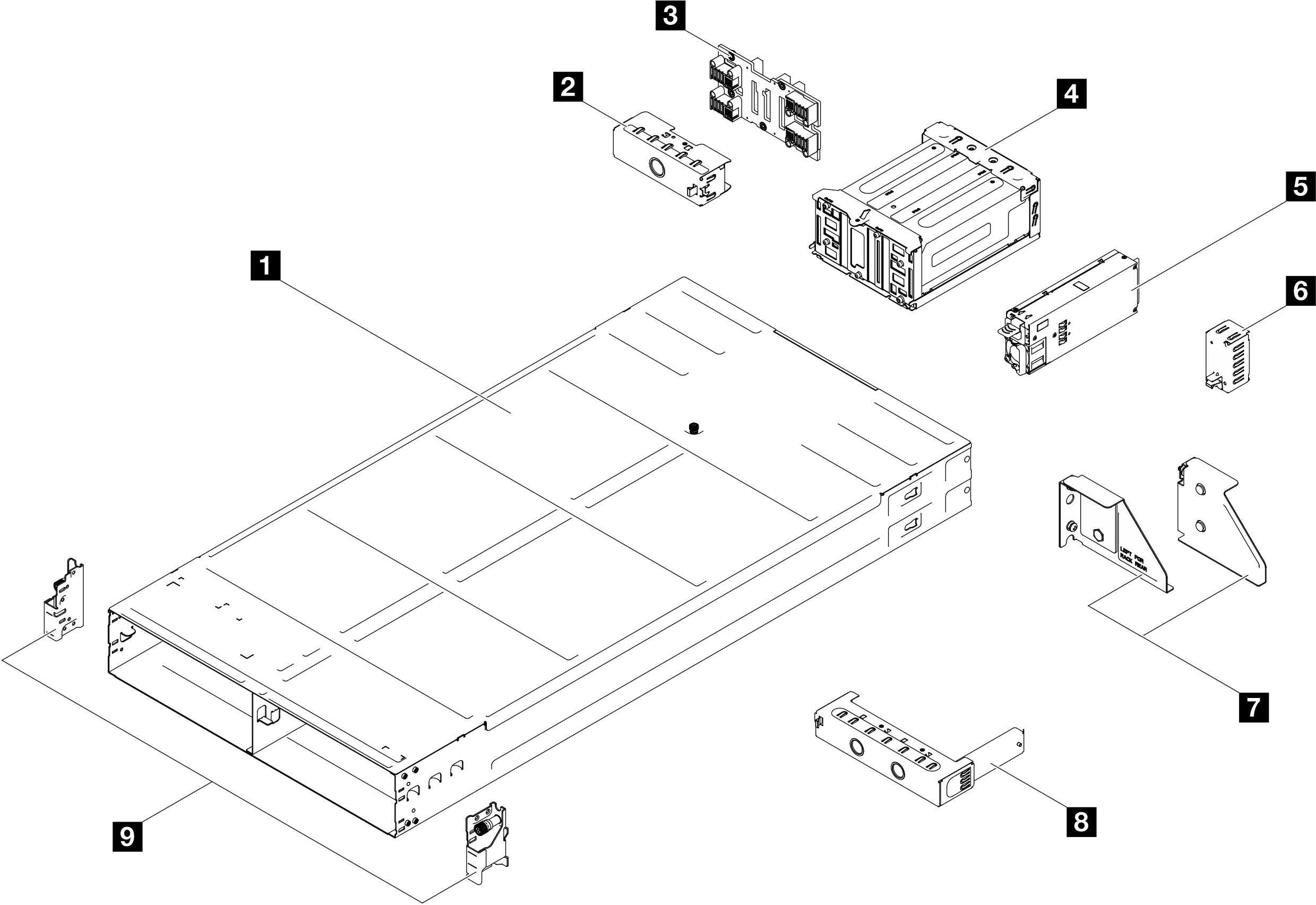
Chassis components
Figure 1. Chassis components


| Description | Type |
|---|---|
| 1 Chassis | T2 |
| 2 Node tray rear filler | T1 |
| 3 Chassis midplane | T2 |
| 4 PSU cage | T1 |
| 5 CRPS power supply unit | T2 |
| 6 PSU filler | T1 |
| 7 Chassis rear shipping brackets (left and right) | T1 |
| 8 Node tray front filler | T1 |
| 9 Chassis front EIA brackets (left and right) | T1 |
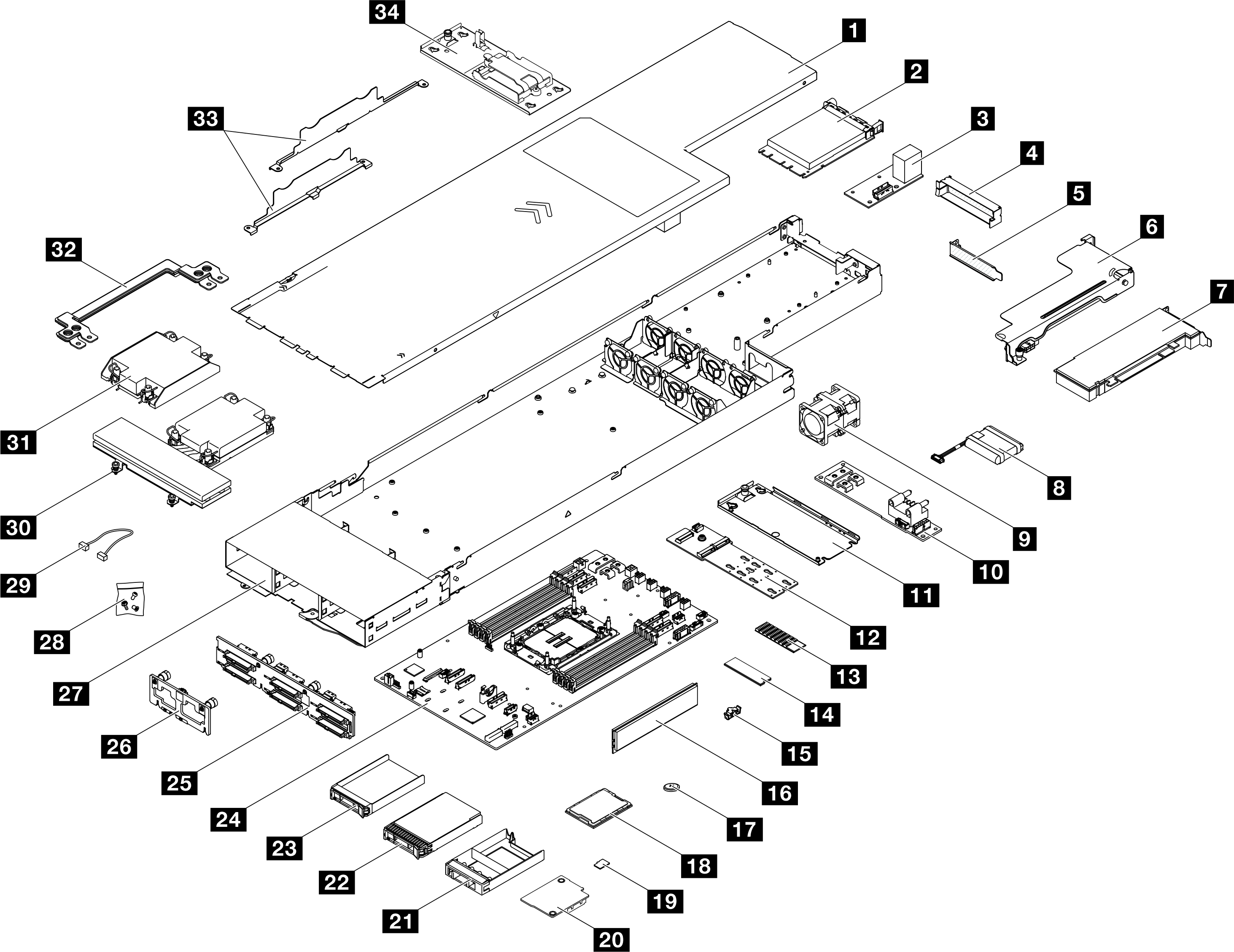
Node components
Figure 2. Node components


| Description | Type | Description | Type |
|---|---|---|---|
| 1 Top cover | T1 | 2 OCP 3.0 module | T1 |
| 3 Rear I/O module | T1 | 4 PCIe riser filler | T1 |
| 5 PCIe filler | T1 | 6 PCIe riser | T2 |
| 7 PCIe adapter | T1 | 8 Flash power module | T1 |
| 9 Fan | T1 | 10 Power distribution board | T2 |
| 11 M.2 boot adapter tray | T1 | 12 M.2 boot adapter | T1 |
| 13 M.2 heat sink | T2 | 14 M.2 drive | T1 |
| 15 M.2 drive retainer | T1 | 16 Memory module | T1 |
| 17 CMOS battery (CR2032) | C | 18 Processor | F |
| 19 MicroSD card | T1 | 20 Firmware and RoT security module | F |
| 21 2.5-inch drive filler | T1 | 22 2.5-inch drive (15 mm) | T1 |
| 23 2.5-inch drive (7 mm) | T1 | 24 System board | F |
| 25 2.5-inch drive backplane | T1 | 26 Front I/O board | T1 |
| 27 Node tray | F | 28 Screws | T1 |
| 29 Cables | T1 | 30 Performance heat sink | F |
| 31 Standard heat sink | F | 32 Power bus bar | T1 |
| 33 Cable walls | T1 | 34 Flash power module holder | T1 |
Give documentation feedback