Remove the power distribution board
Use this information to remove the power distribution board.
About this task

To avoid a shock hazard:
- Connect all power cords to a properly wired and grounded electrical outlet/source.
- Connect any equipment that will be attached to this product to properly wired outlets/sources.
- When possible, use one hand only to connect or disconnect signal cables.
- Never turn on any equipment when there is evidence of fire, water, or structural damage.
- The device might have more than one power cord, to remove all electrical current from the device, ensure that all power cords are disconnected from the power source.
Read Installation Guidelines and Safety inspection checklist to ensure that you work safely.
Turn off the corresponding DWC tray that you are going to perform the task on.
Disconnect all external cables from the enclosure.
Use extra force to disconnect QSFP cables if they are connected to the solution.
To avoid damaging the water loop, always use the water loop carrier when removing, installing or folding the water loop.
| Screwdriver Type | Screw Type |
|---|---|
| Torx T10 head screwdriver | Torx T10 screw |
| Torx T30 head screwdriver | Torx T30 screw |
| Phillips #1 head screwdriver | Phillips #1 screw |
| Phillips #2 head screwdriver | Phillips #2 screw |
- A video of this procedure is available at YouTube.
Procedure
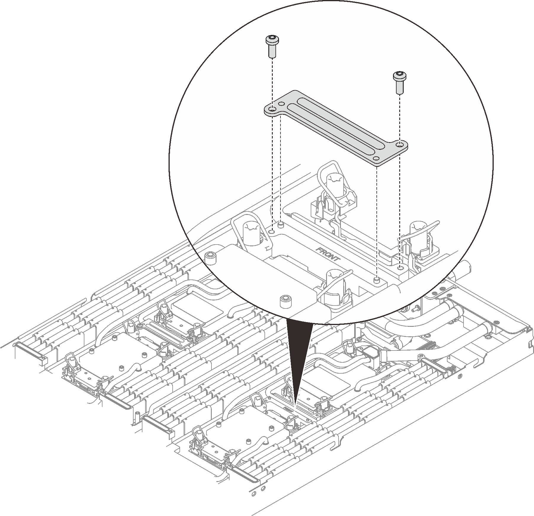
- Remove two Torx T10 screws (per node); then, remove the VR (voltage regulator) clamp plate out of the node.Figure 1. VR clamp plate removal
- Remove water loop screws (9x Torx T10 screws per node) with a torque screwdriver set to the proper torque.NoteFor reference, the torque required for the screws to be fully tightened/removed is 5.0+/- 0.5 lbf-in, 0.55+/- 0.05 N-M.Figure 2. Water loop screw removal
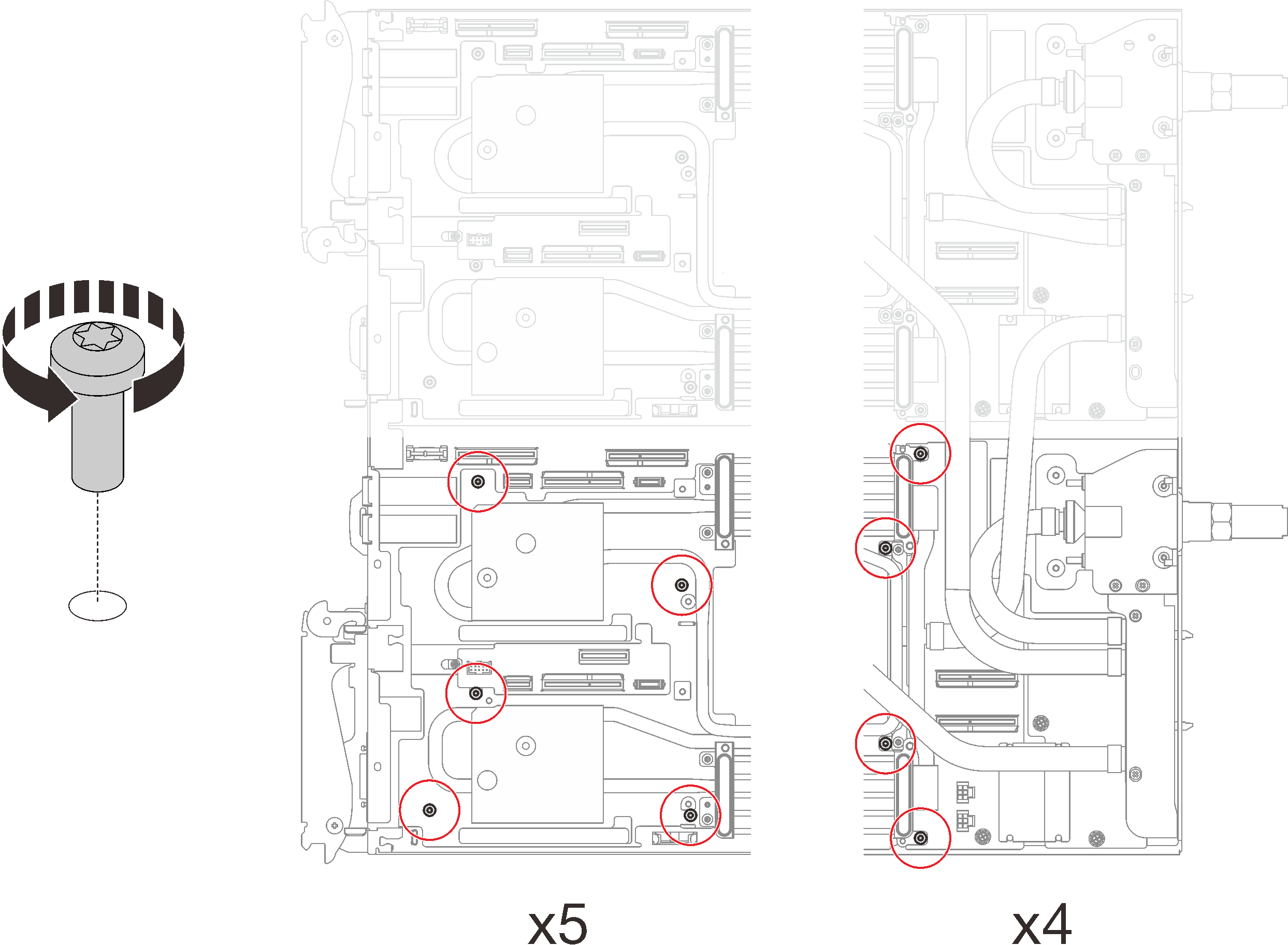
- Remove the following screws to loosen the quick connect.
Two Torx T10 screws (per node) on the quick connect.
Five Torx T10 screws (per node) on the rear of the node.
Figure 3. Quick connect screw removal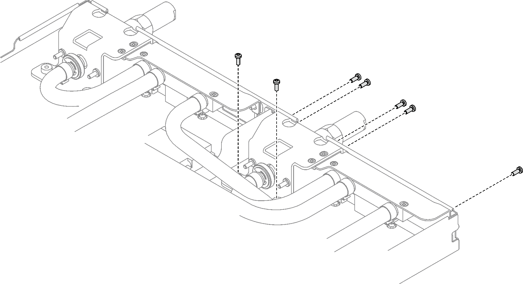
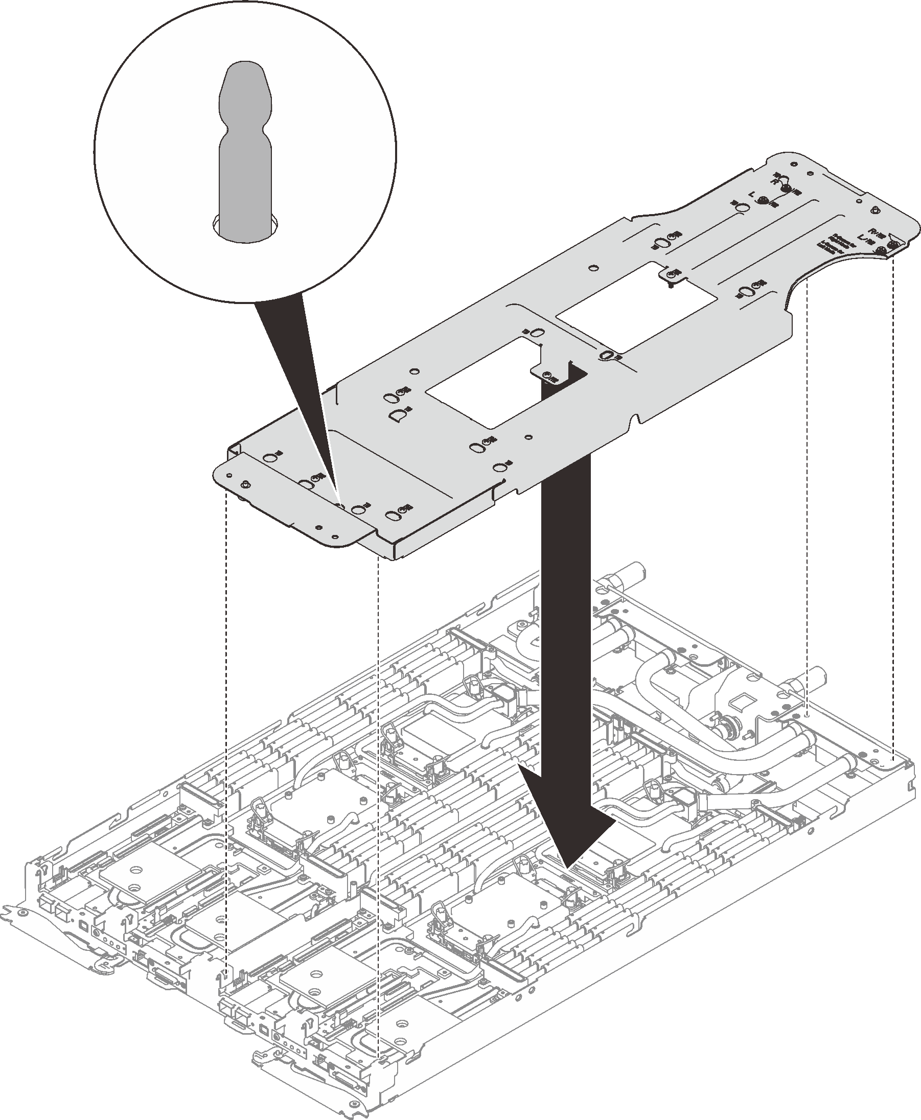
- Orient the water loop carrier with the guide pin; then, gently put the water loop carrier down and ensure it is seated firmly on the water loop.Figure 4. Water loop carrier installation
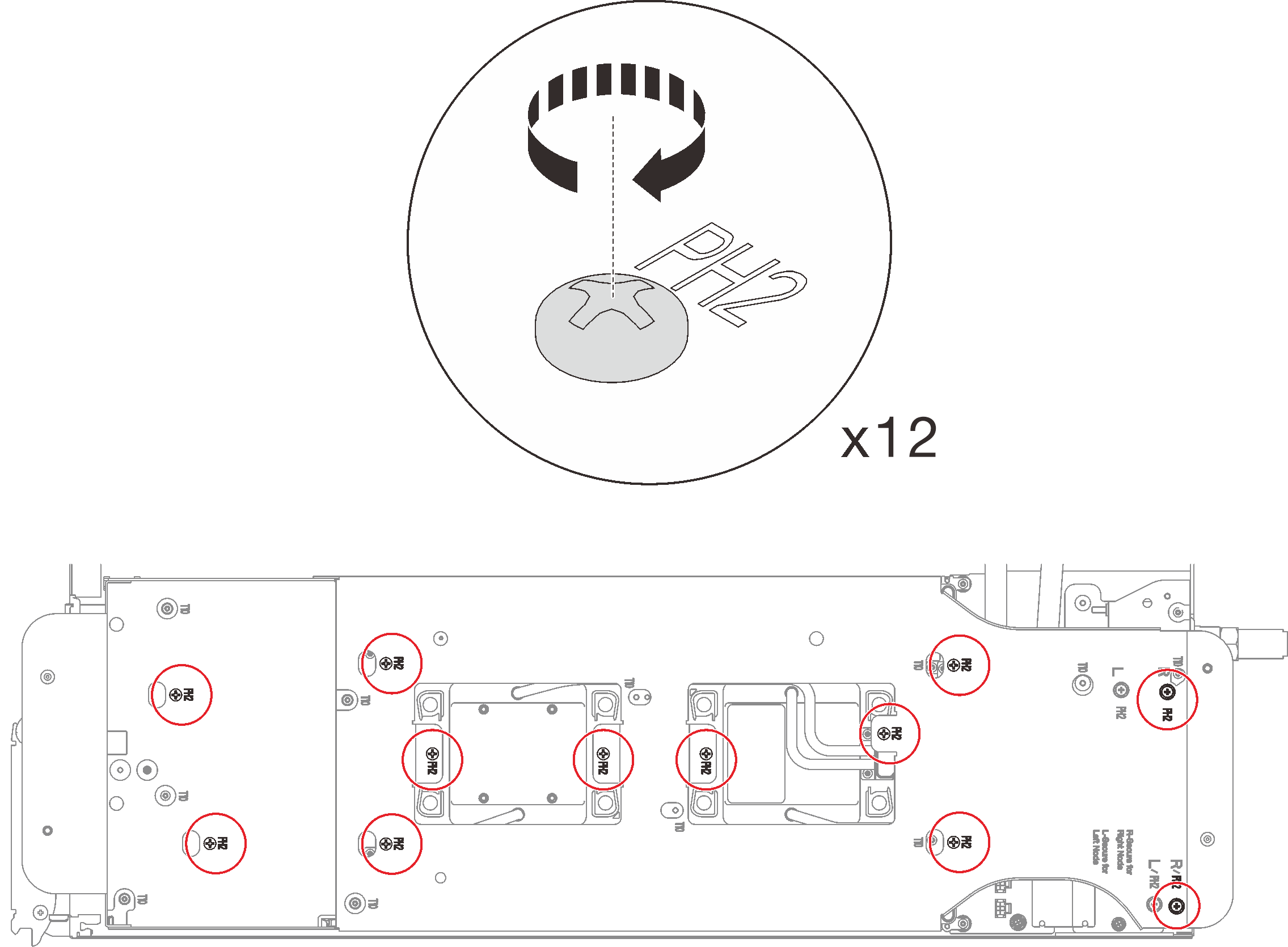
- Tighten water loop carrier screws (12x Phillips #2 screws per node).Figure 5. Water loop carrier screws installation
- Loosen processors properly.
 Fully loosen all Torx T30 captive screws (8x Torx T30 captive screws per node) on cold plates with a general screwdriver until they stop, following the removal sequence shown on the cold plate label.NoteFor reference, the torque required for the screws to be fully tightened/removed is 10+/- 2.0 lbf-in, 1.1+/- 0.2 N-m.AttentionTo prevent damage to components, make sure that you follow the indicated loosening sequence.
 Rotate all anti-tilt wire bails (8x anti-tilt wire bails per node) inwards to the unlocked position.
Figure 6. Loosening processors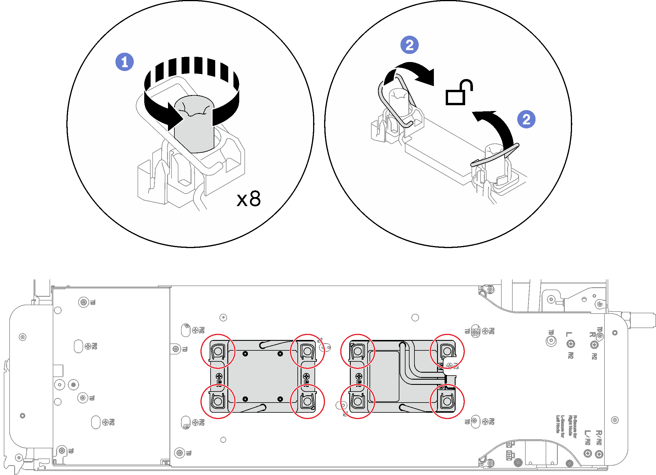
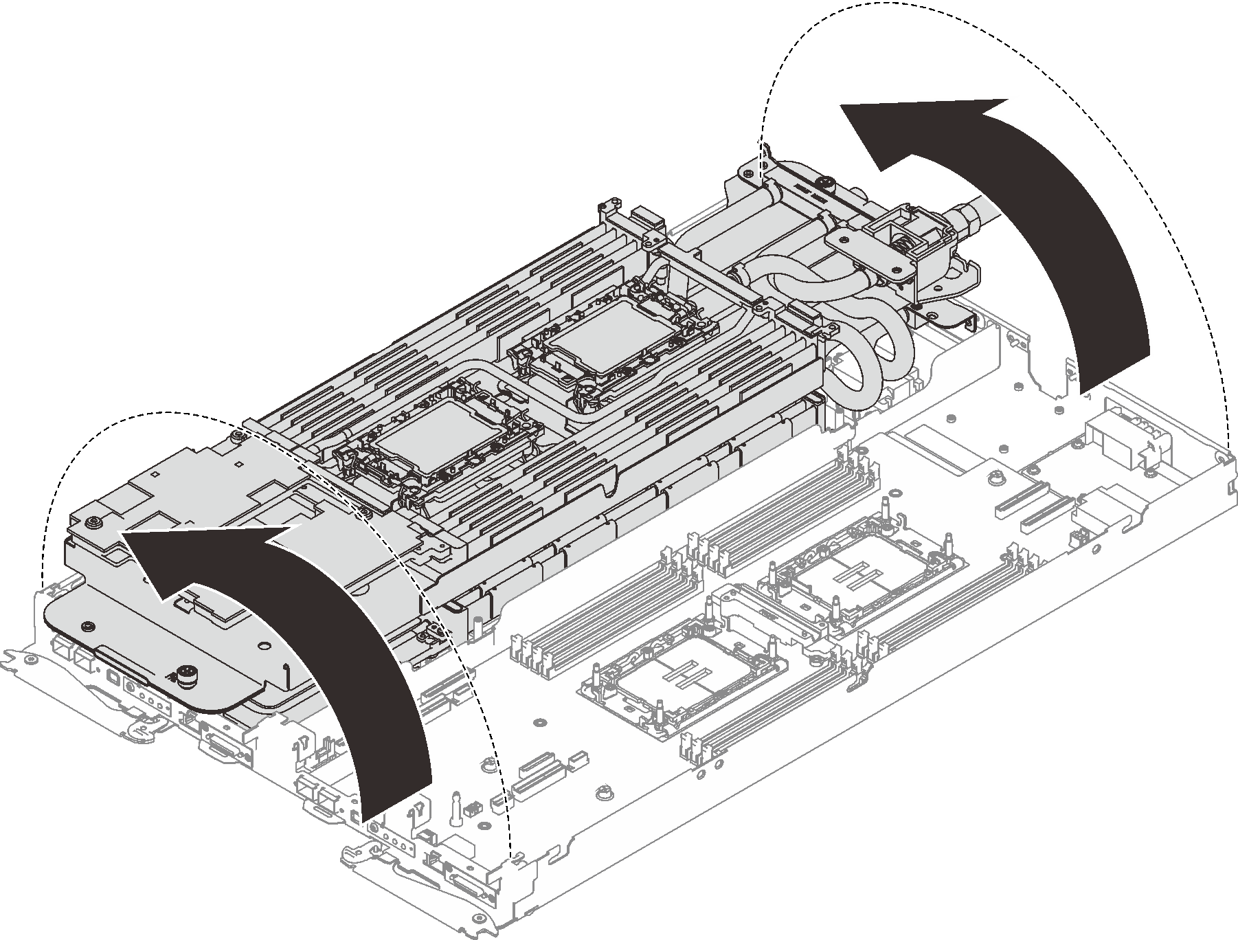
- Carefully rotate the water loop so one half is sitting on top of the other half.Figure 7. Folding the water loop
- Remove the power distribution board.
- Remove the five Phillips #1 screws (per node).
- Gently pull the power distribution board connector to disconnect it from the system board.
 Carefully pull the power distribution board inwards to disengage it from the node.
NoteUse a 3/16" hex head screwdriver to ensure the proper removal and installation.
Figure 8. Power distribution board removal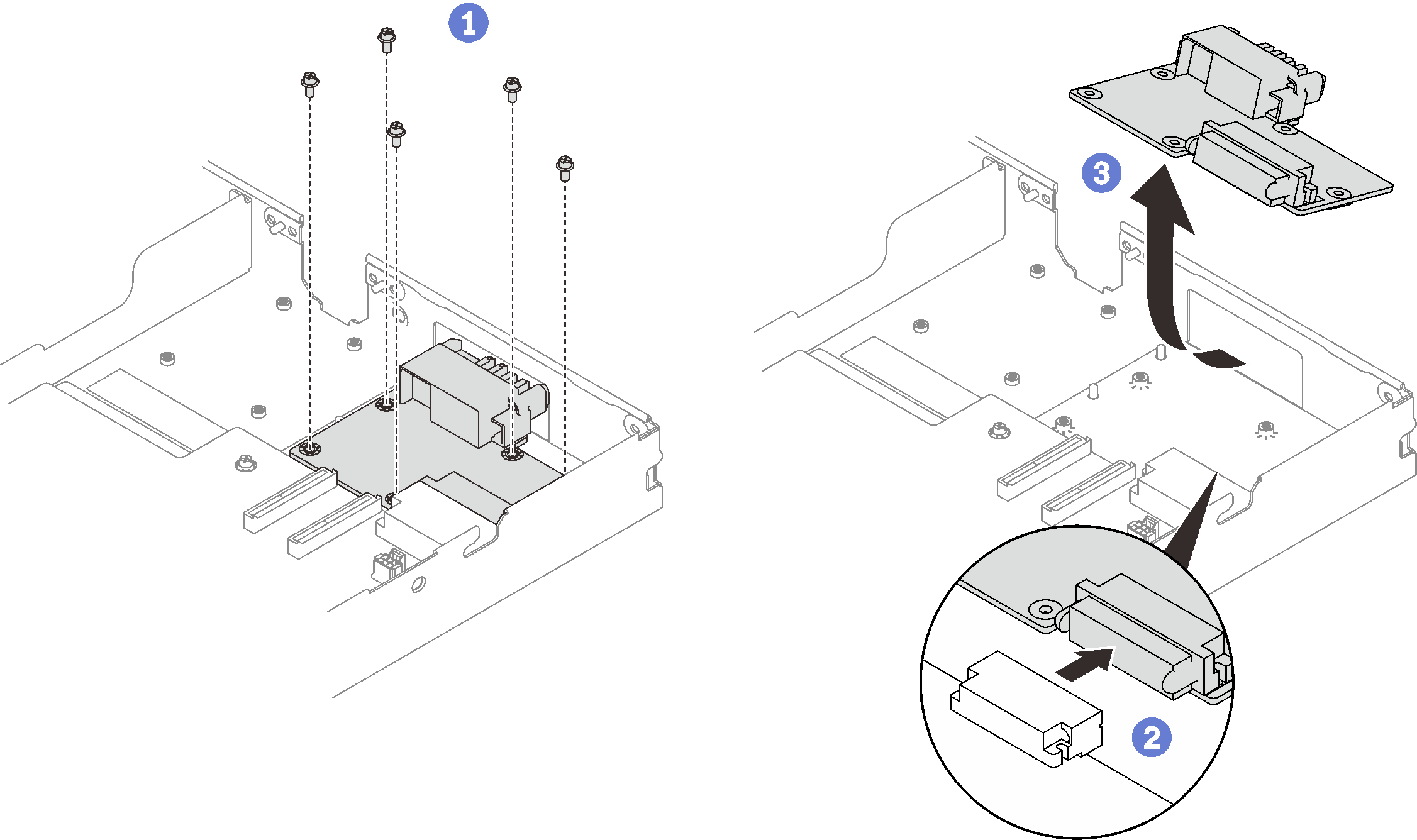
If you are instructed to return the component or optional device, follow all packaging instructions, and use any packaging materials for shipping that are supplied to you.