PCIe adapter in compute node cable routing
Use this information to route the cables for PCIe adapters in the compute node.
Refer to the following cable routing instruction according to your PCIe adapter hardware design and your system configuration.
| PCIe adapter with an Aux Kit | PCIe adapter with an Aux Cable | |||
|---|---|---|---|---|
| Share I/O configuration | Socket direct configuration | Share I/O configuration | Socket Direct configuration | |
| ConnectX-6 | √ | √ | ||
| ConnectX-7 NDR 200 | √ | √ | ||
| ConnectX-7 NDR 400 | √ | √ | √ | √ |
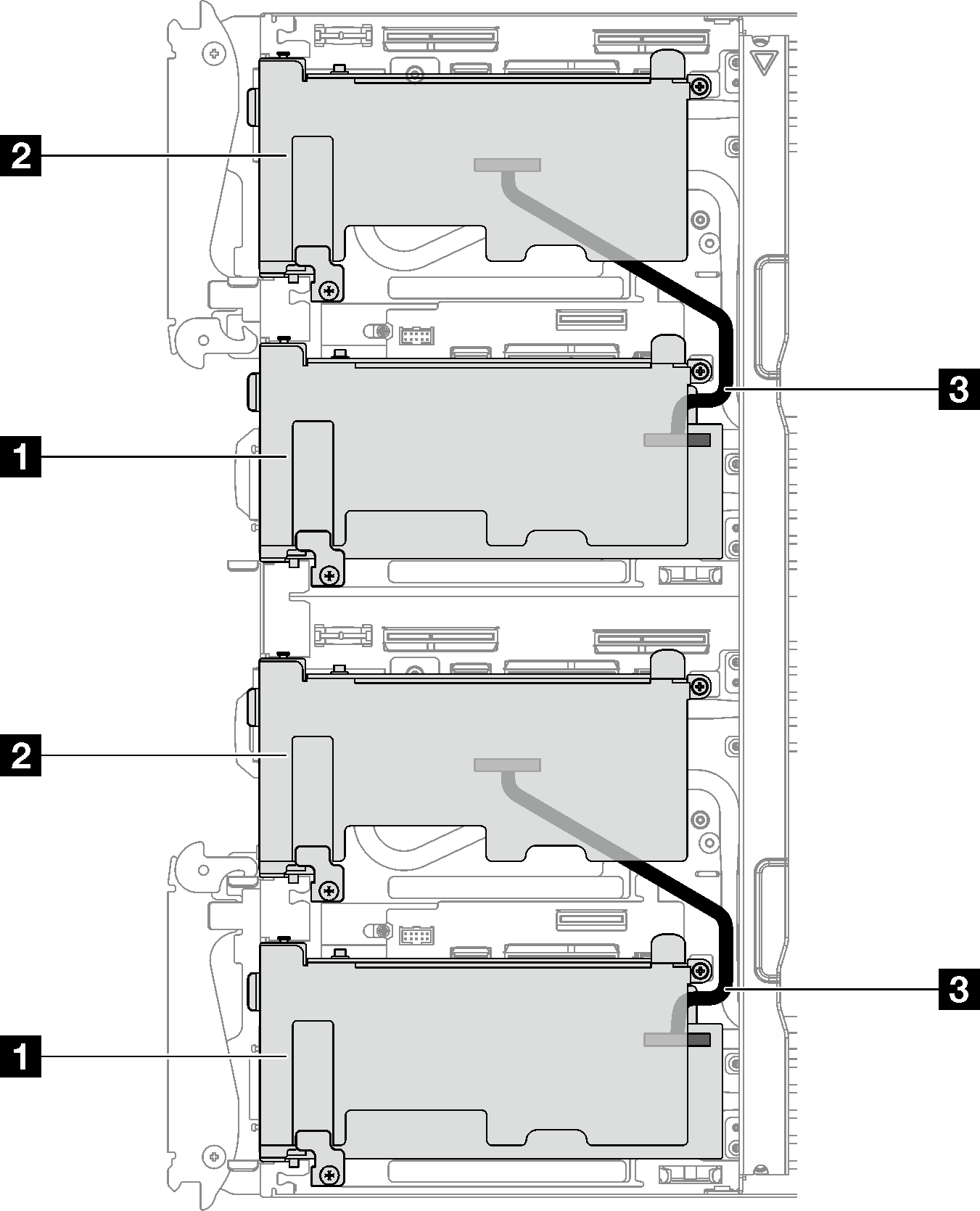
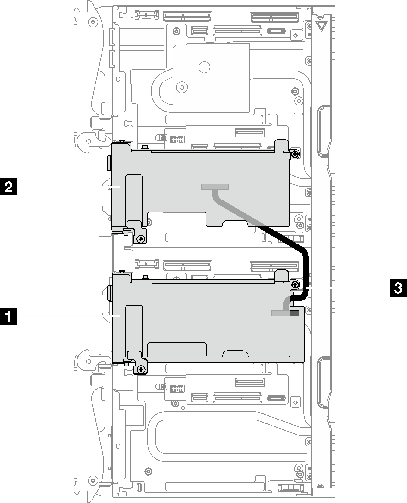
PCIe adapter with an Aux Kit – Socket direct configuration
Figure 2. Socket direct configuration cable routing


| 1 Main adapter with riser |
| 2 Auxiliary adapter with riser |
| 3 250 mm IPEX cable |
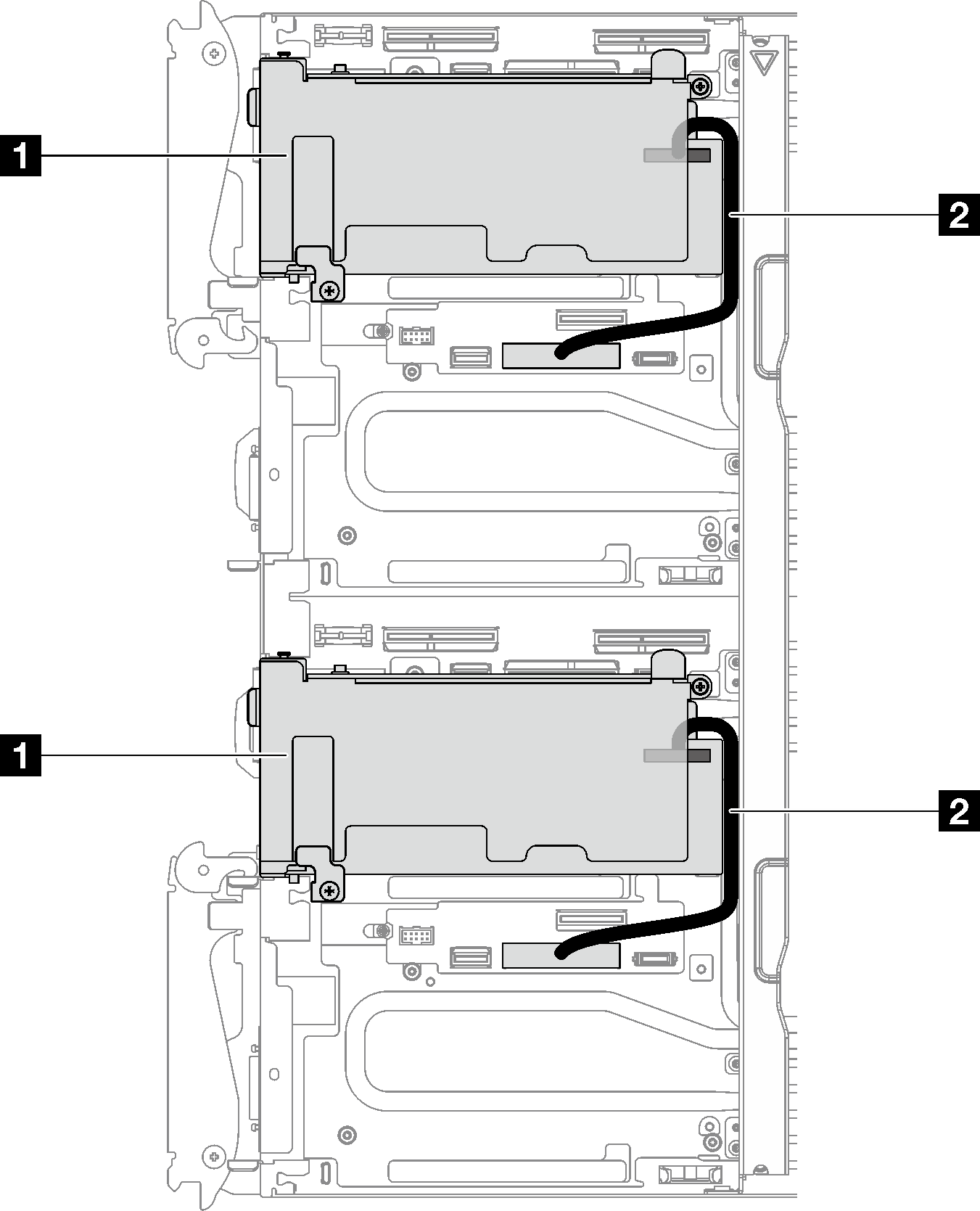
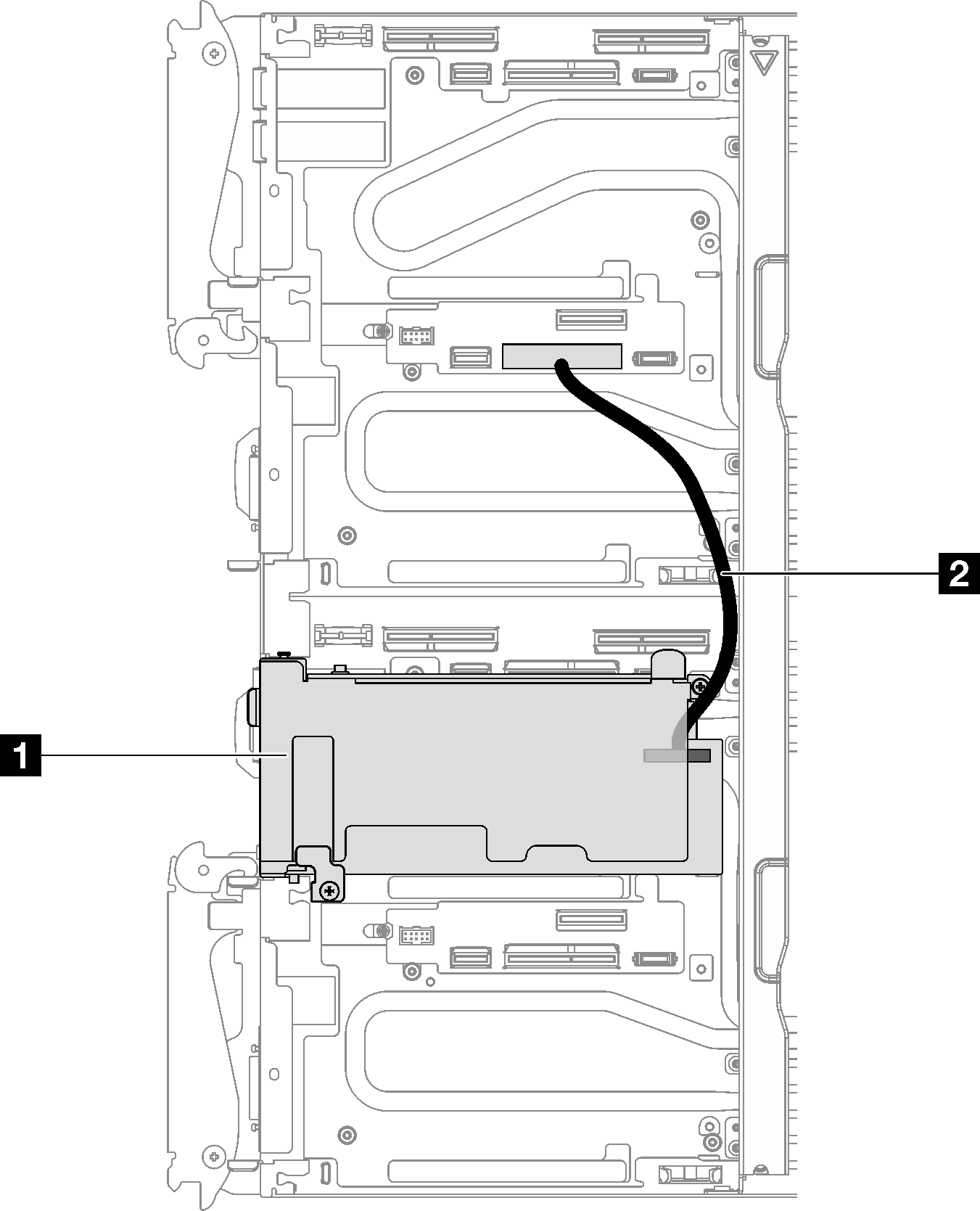
PCIe adapter with an Auxiliary Cable – Socket direct configuration
Figure 4. Socket direct configuration cable routing


| 1 Main adapter with riser |
| 2 Auxiliary cable (190 mm). The cable is directly connected to PCIe riser 1 slot on the system board of the left node or right node. |
Give documentation feedback

