Install the braided cables
Use this information to install the braided cables
About this task
Read Installation Guidelines and Safety inspection checklist to ensure that you work safely.
Turn off the corresponding DWC tray that you are going to perform the task on.
Disconnect all external cables from the enclosure.
Use extra force to disconnect QSFP cables if they are connected to the solution.
To avoid damaging the water loop, always use the water loop carrier when removing, installing or folding the water loop.
Procedure
- Identify the braided cables.
Shielding cage Braided cable 1 (connected with braided cable 2 by Y cable) Braided cable 2 (connected with braided cable 1 by Y cable) Braided cable 3 Braided cable 4 (attached shielding cage is smaller than braided cable 3) Figure 1. Braided cable 1/2, 3, and 4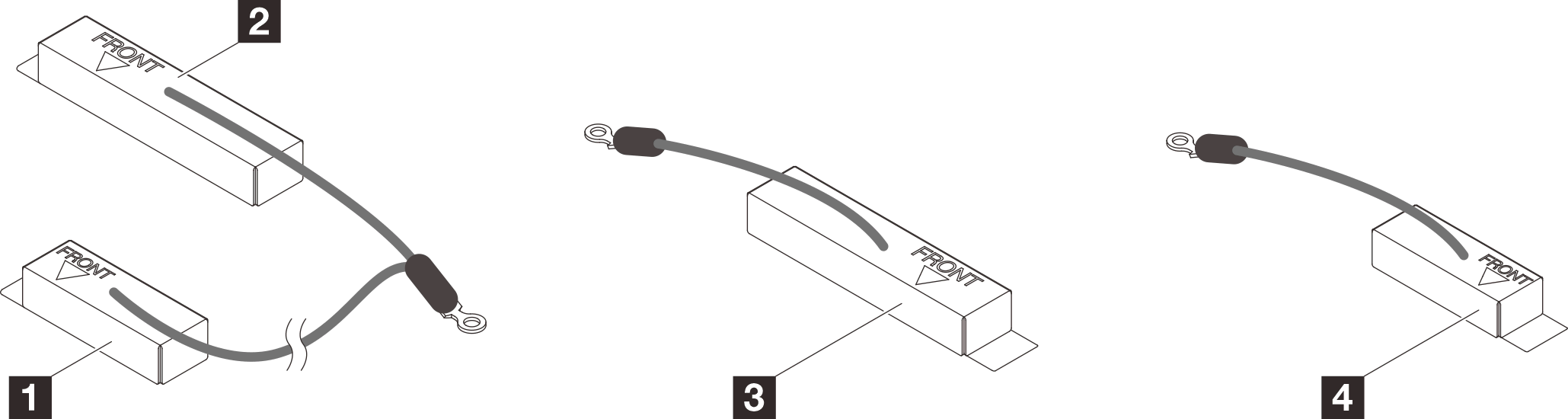
- Align braided cable 1/2 and braided cable 3 to the screw holes on system board. Make sure the ring terminals of the cable are placed in the angle shown below.
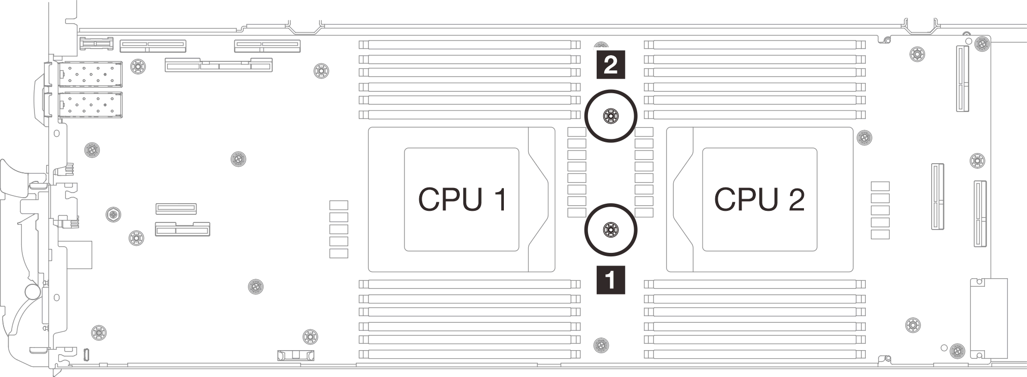
1 Screw hole for braided cable 3 2 Screw hole for braided cable 1/2 Figure 2. Aligning braided 1/2 and 3 to the screw hole on system board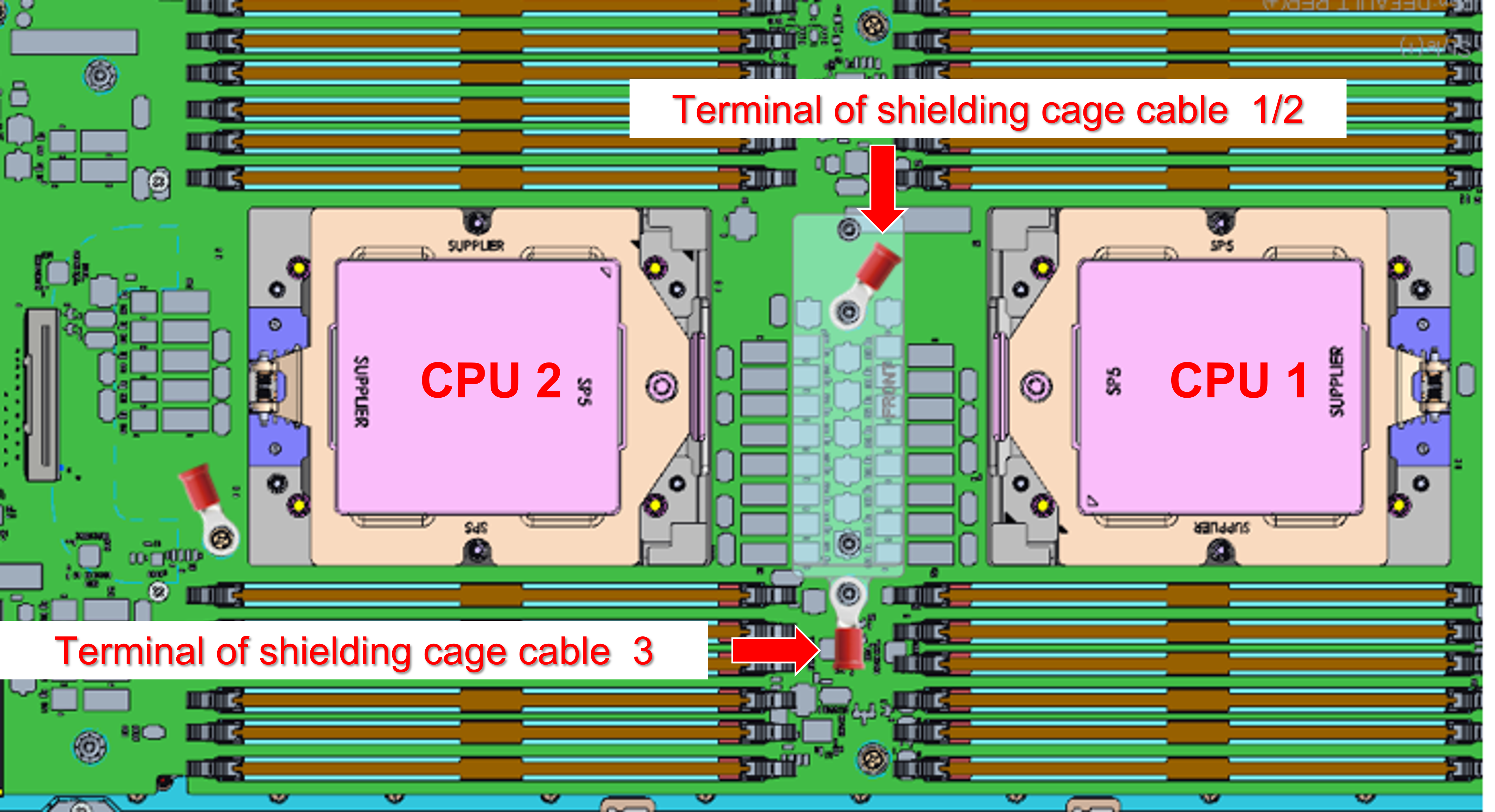
- Install braided cable 1/2 and 3.
 Keep the FRONT marking on the VR conduction plate facing the front of the server. Then, place the VR conduction plate on top of the two cable ring terminals.
 Slightly press down the VR conduction plate.AttentionThe following items will be secured by screw. Make sure they are aligned and do not block each other.
Screw hole on the system board
The hole on the ring terminal of the shielding cage cable
Screw hole on the VR conduction plate
Figure 3. Aligning VR conduction plate, braided cables, and system board screw holes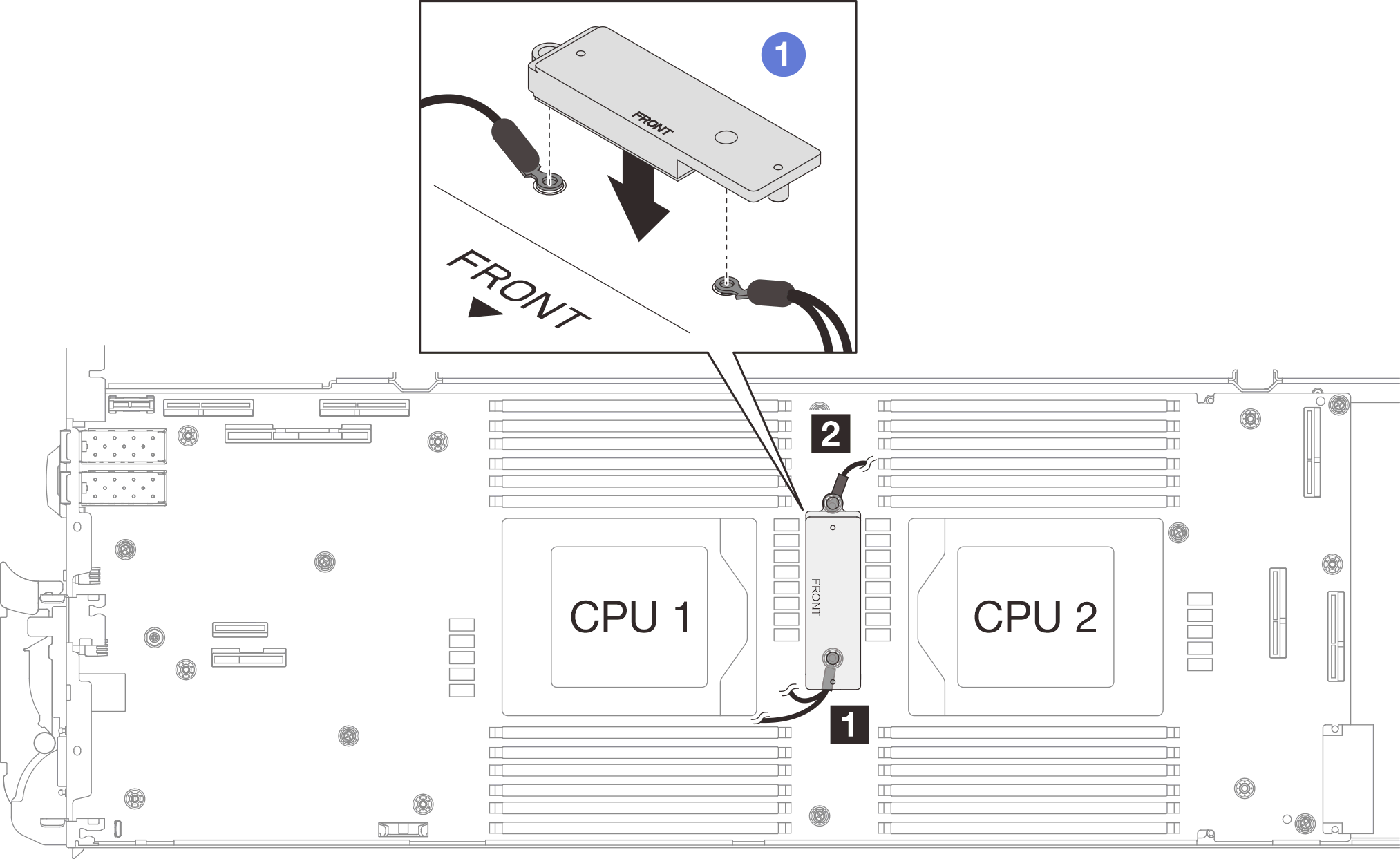 Figure 4. Pressing on the VR conduction plate
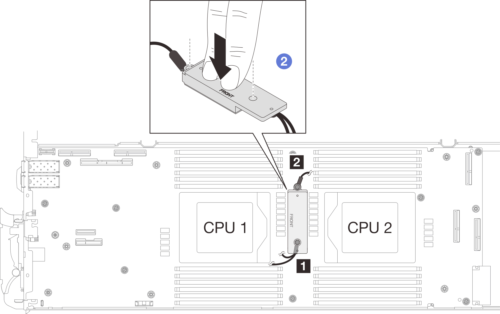
 While pressing down the VR conduction plate, place the screws into the two screw holes on the VR conduction plate. Then, fasten the two screws to secure the cables to the system board. DO NOT fasten the screws until both screws are placed into the VR conduction plate.Figure 5. Installing braided cable 1/2 and 3
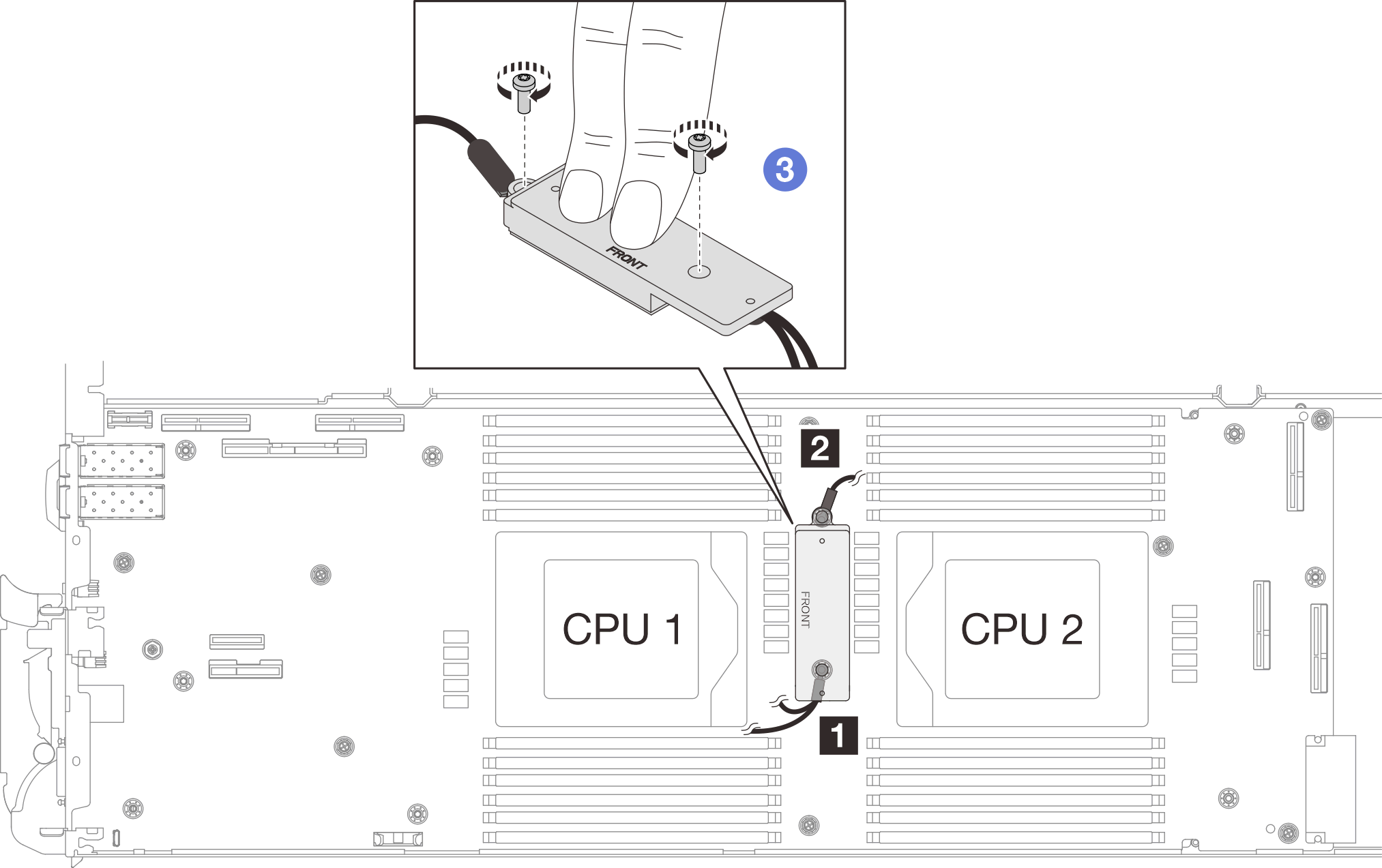
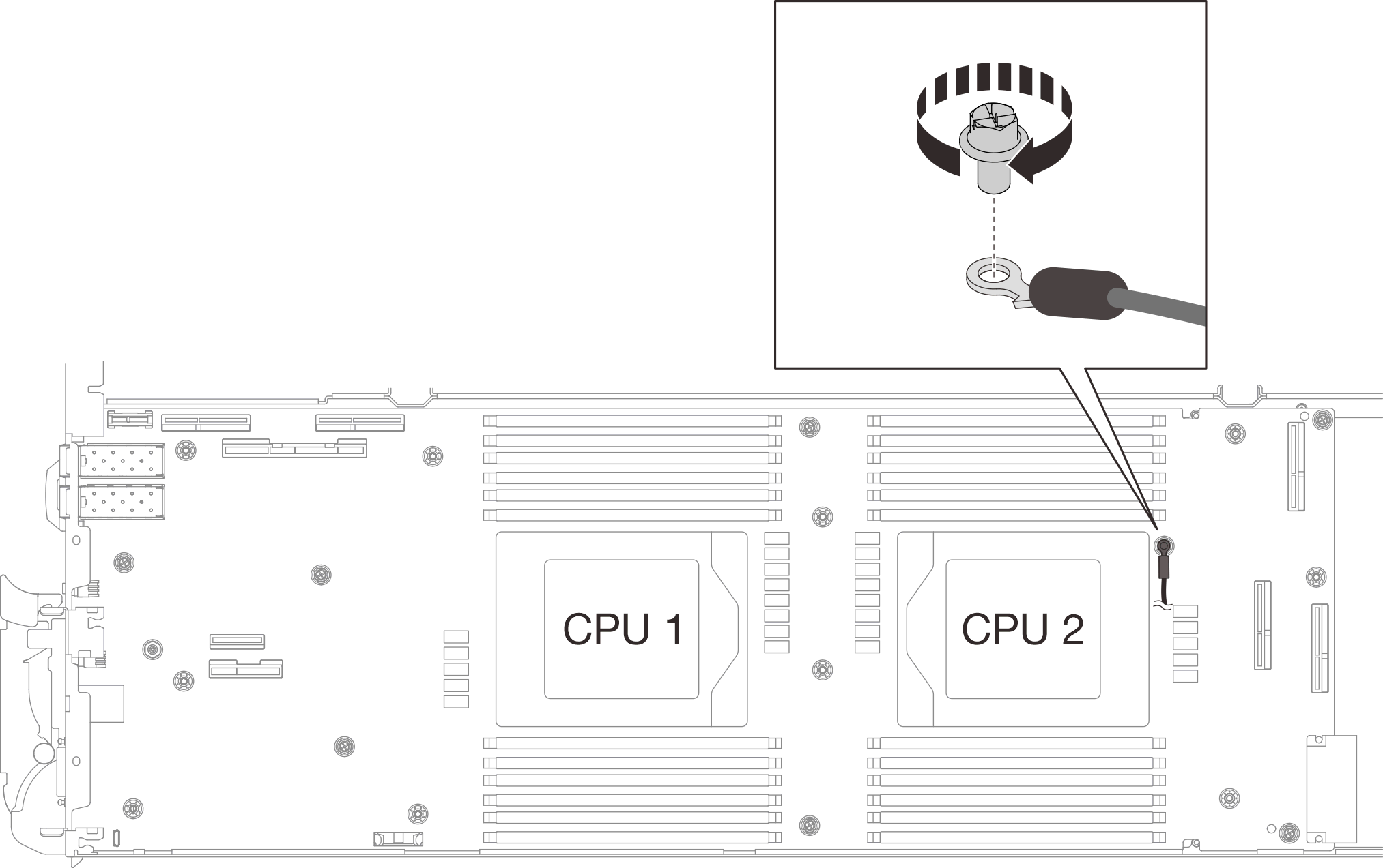
- Align braided cable 4 to the screw holes on system board as shown below. Make sure the ring terminal of the cable is placed in the angle shown below. Fasten the screw to secure the braided cable to the system board.Figure 6. Installing braided cable 4
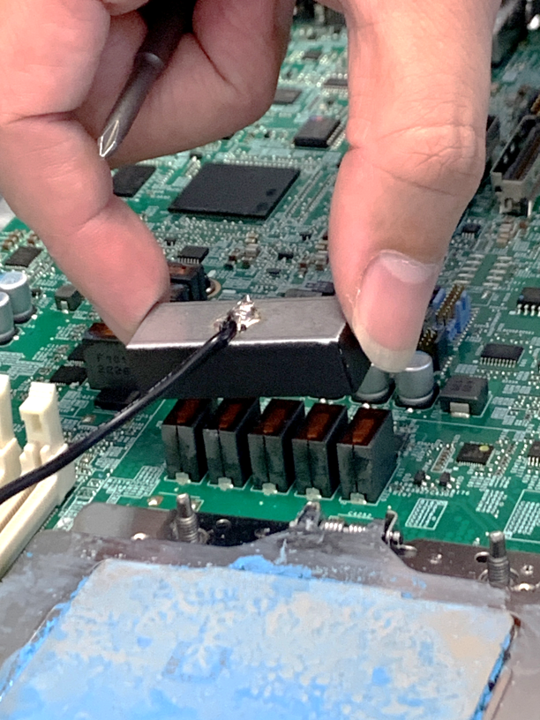
- From the inside of the shielding cages, hold the tab and peel off the adhesive tapes. Complete the step for all four shielding cages.
1 Adhesive tape tab Figure 7. Peeling off the adhesive tape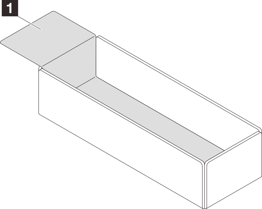
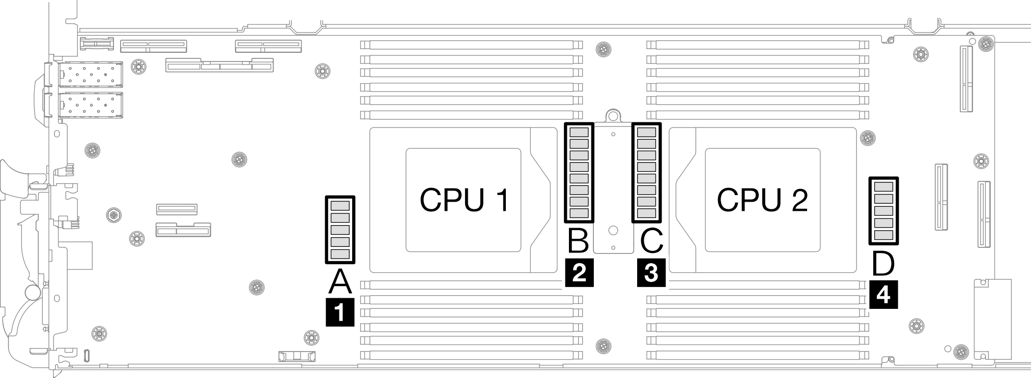
- Cover the inductors on system board with shielding cages. Follow the inductors and braided cable mapping table below.AttentionAfter covering the inductors with shielding cages,
DO NOT remove the shielding cages from the system board to avoid system board damages. Table 1. Shielding cage and inductors mapping table Shielding cage Inductor on the system board to be covered by the shielding cage Shielding cage 1 (Y cable) A Shielding cage 2 (Y cable) B Shielding cage 3 C Shielding cage 4 (smaller cage) D Figure 8. Shielding cage 1, 2, 3, and 4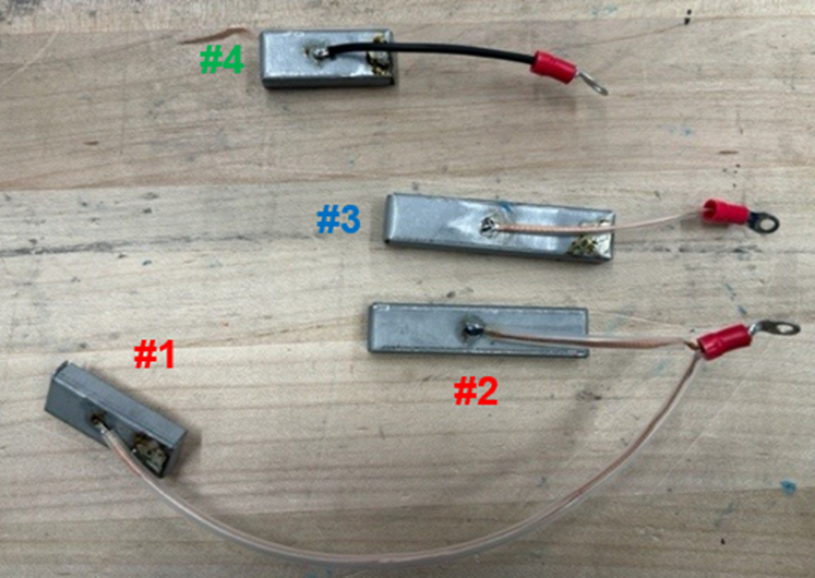 Figure 9. Inductors locations on the system board
- Make sure the FRONT marking on the cage points at the front of the tray.Figure 10. Front marking on the cage pointing at the front
- Attach the inside of the cage to the inductor attaching point. In the graphic below, the dotted lines specify the inductor attaching points for the inside of the cage. The inductor attaching point is where the inside of the cage and the inductors attach to each other seamlessly without any gap.Note
Shielding cage 1 and 4: one attaching point
Shielding cage 2 and 3: two attaching points
Figure 11. Inductor attaching points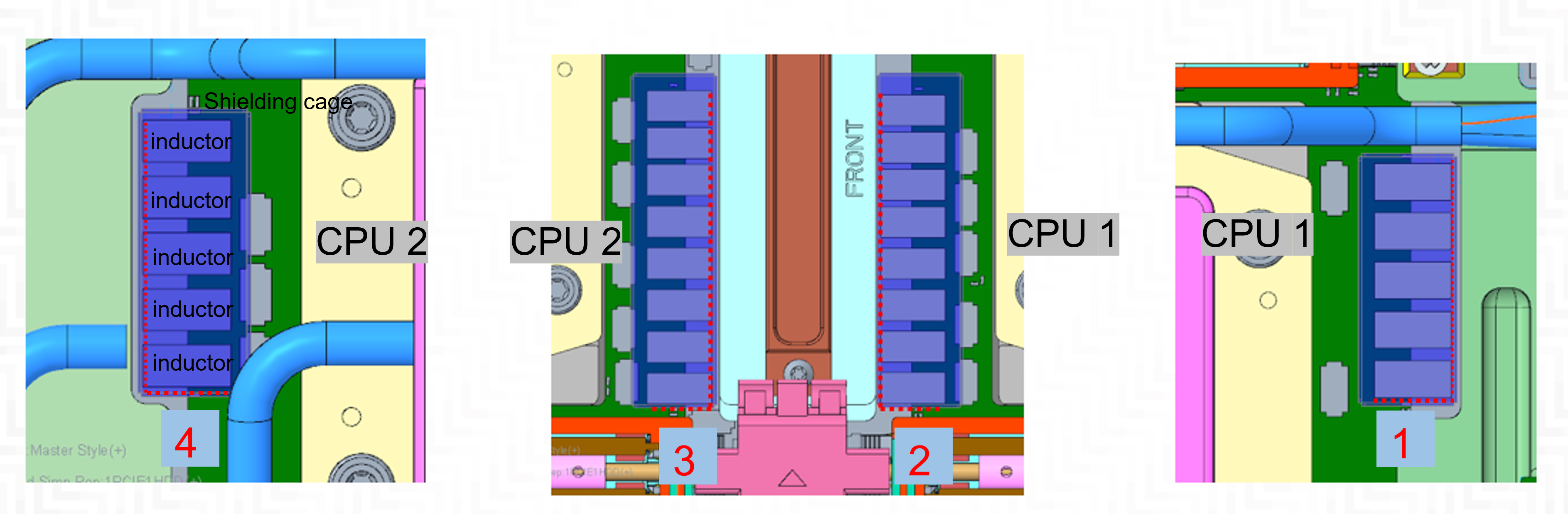
- Keep the cage attached to the inductor attaching point and make sure the inductors are completely covered; then, lower the cage into the system board.NoteFor the non-attaching-point side of cage 1 and 4, balance the gap between the inside of the cage and inductors.Figure 12. Covering the inductors with the shielding cage
- Make sure the FRONT marking on the cage points at the front of the tray.
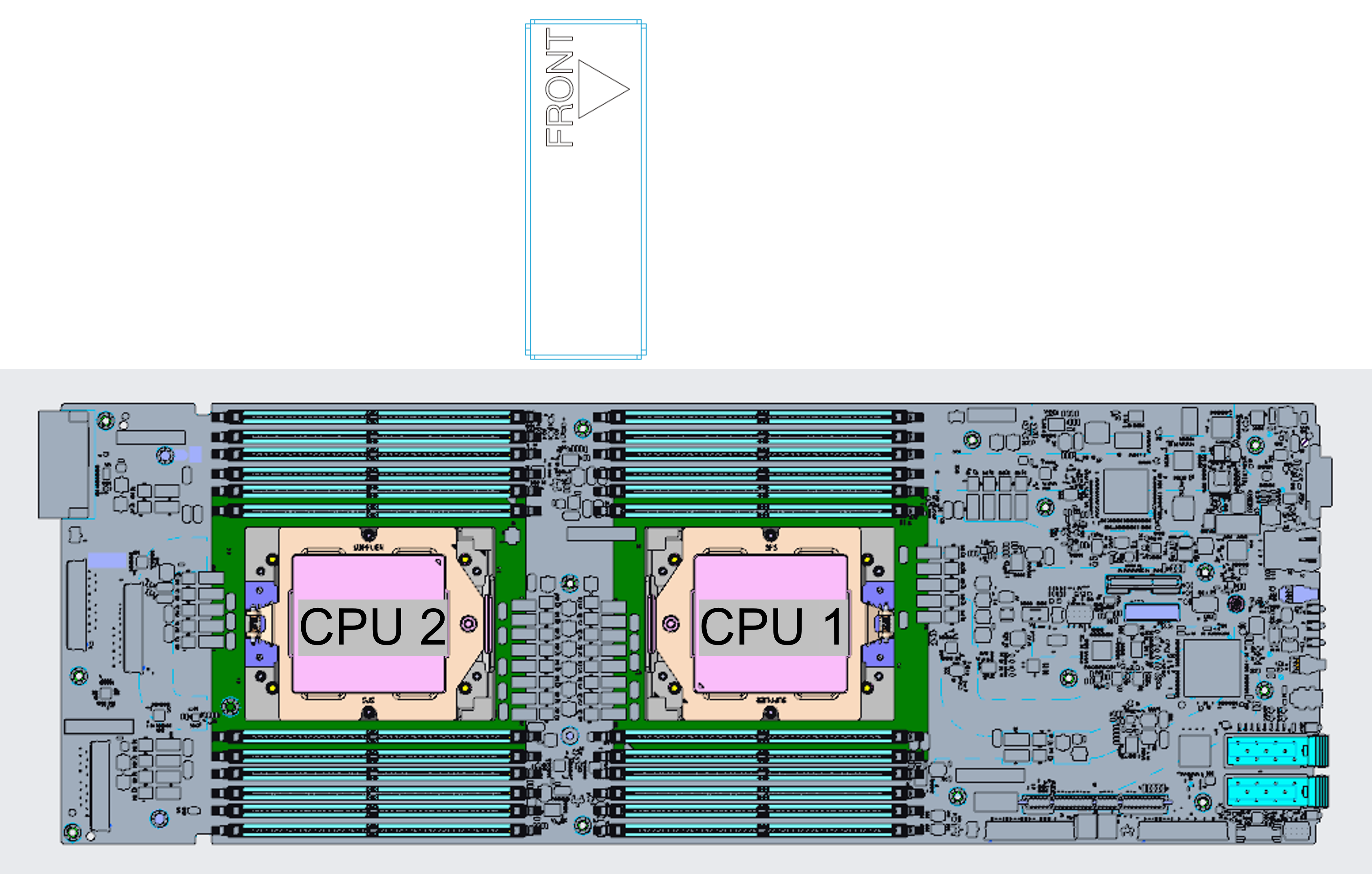
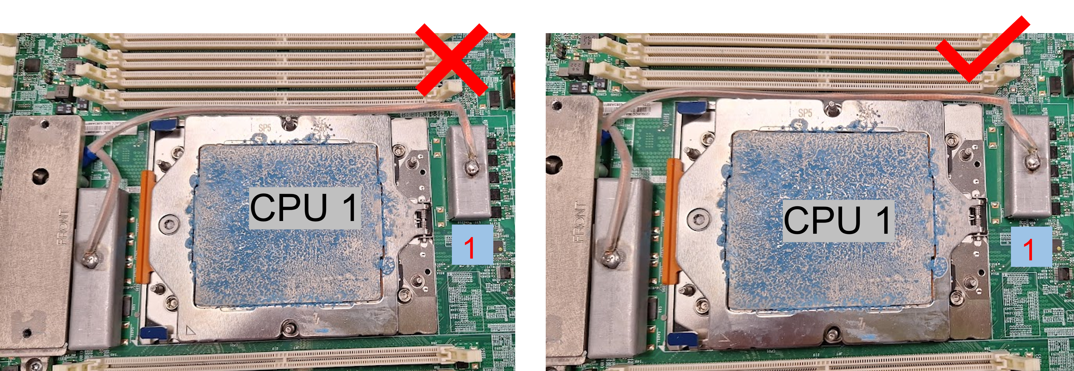
- Route the shielding cage 1 cable between CPU 1 socket and the DIMM slots. Make sure all shielding cage cable are cleared from CPU sockets, DIMM slots, and other system board connectors.Note
Make sure the FRONT marking on the cage points at the front of the tray.
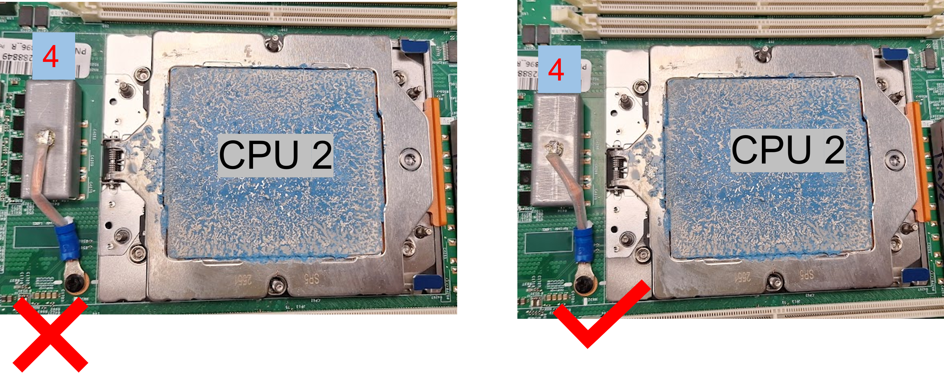
Figure 13. Cable routing for shielding cages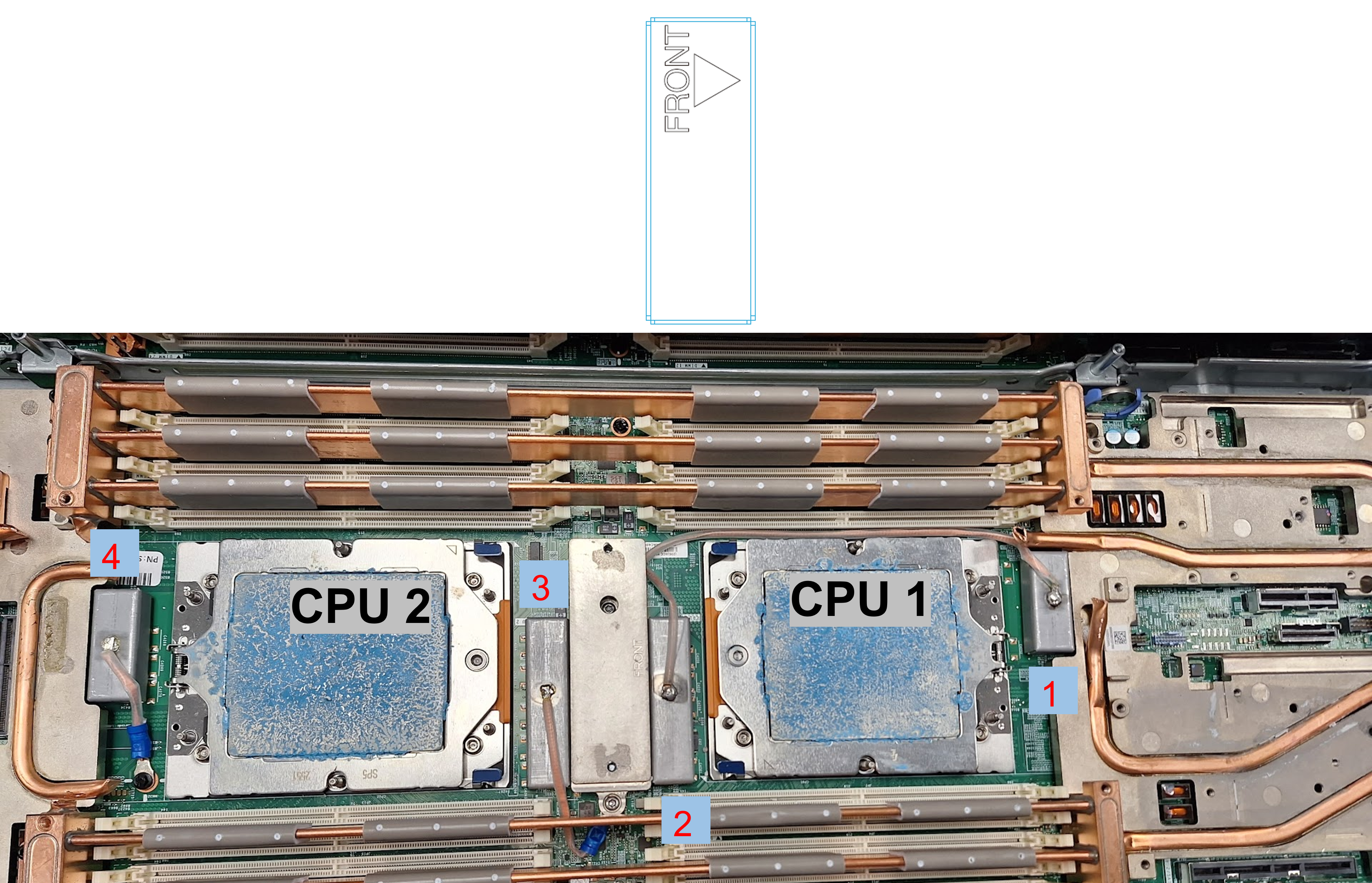
The shielding cage 1 cable should be angled toward the CPU 1.
The shielding cage 4 cable should be angled toward the CPU 2.
Proceed to the next chapter