Kabelführung der Rückwandplatine für 2,5‑Zoll-Laufwerke
Verwenden Sie diesen Abschnitt, um die Kabelführung für die Rückwandplatine für 2,5‑Zoll‑Laufwerke zu verstehen.
Wählen Sie je nach Position der Rückwandplatine für Laufwerke den entsprechenden Kabelführungsplan aus:
Rückwandplatine 1
Abbildung 1. Kabelführung für Rückwandplatine 1
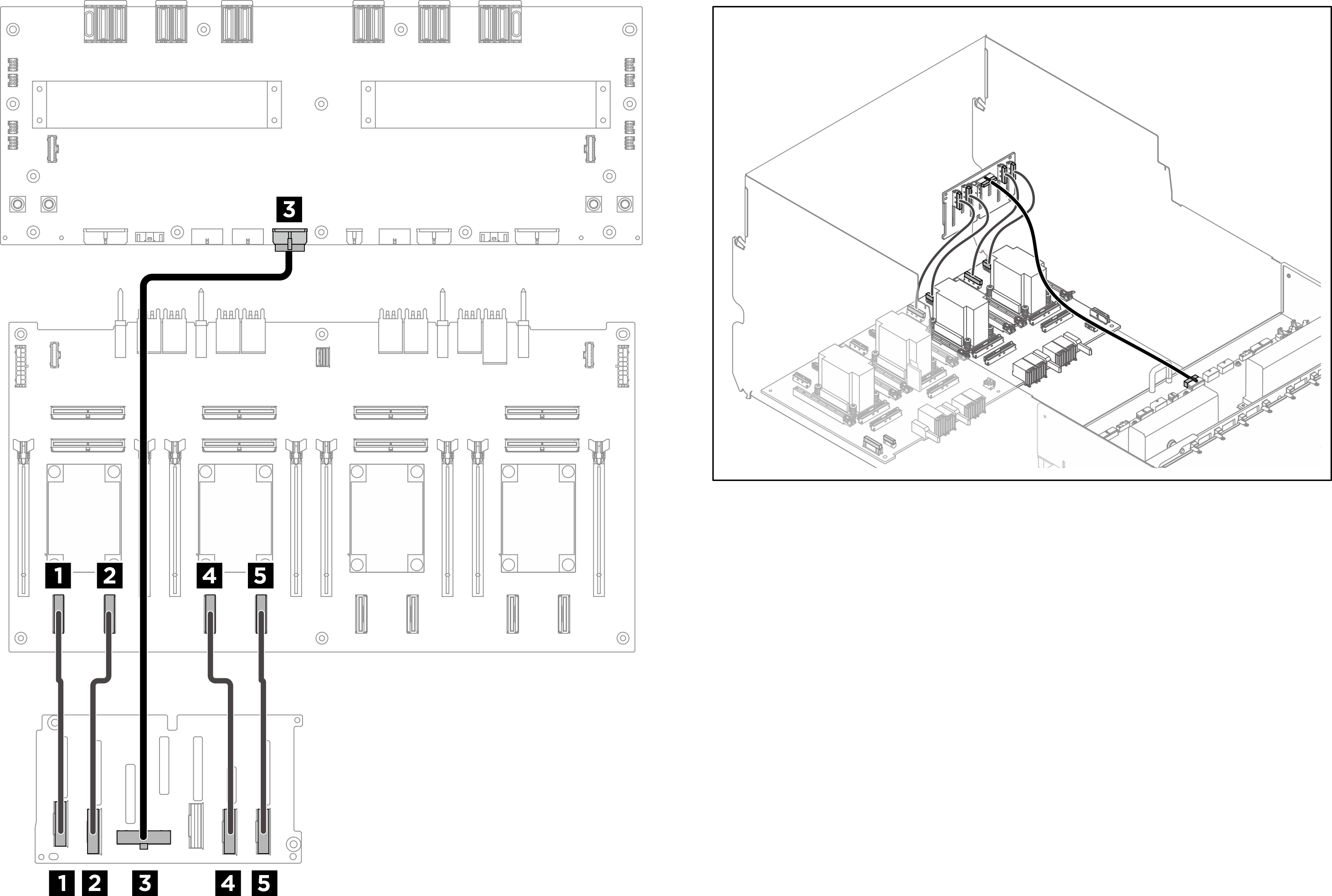
| Kabel | Vom | Zu | Etikett |
|---|---|---|---|
| 1 | Rückwandplatine 1: NVMe-Anschluss 0-1 | PCIe-Switch-Platine: NVMe-Anschluss 1 (NVME1) |
|
| 2 | Rückwandplatine 1: NVMe-Anschluss 2-3 | PCIe-Switch-Platine: NVMe-Anschluss 2 (NVME2) |
|
| 3 | Rückwandplatine 1: Netzteilanschluss | Stromversorgungsplatine: Netzteilanschluss der Rückwandplatine 1 (BP1 PWR) | – |
| 4 | Rückwandplatine 1: NVMe-Anschluss 4-5 | PCIe-Switch-Platine: NVMe-Anschluss 3 (NVME3) |
|
| 5 | Rückwandplatine 1: NVMe-Anschluss 6-7 | PCIe-Switch-Platine: NVMe-Anschluss 4 (NVME4) |
|
Rückwandplatine 2
Abbildung 2. Kabelführung für Rückwandplatine 2
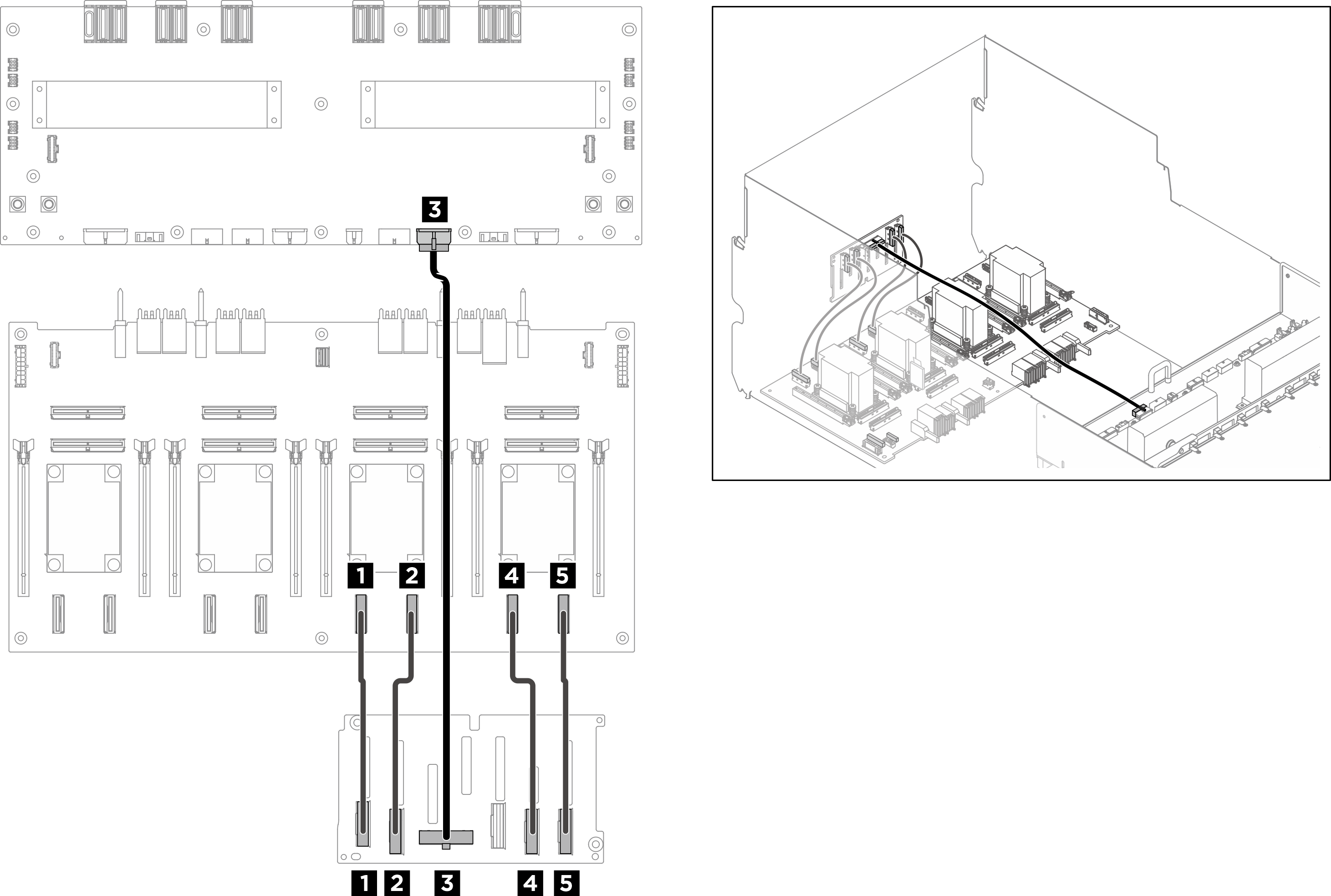
| Kabel | Vom | Zu | Etikett |
|---|---|---|---|
| 1 | Rückwandplatine 2: NVMe-Anschluss 0-1 | PCIe-Switch-Platine: NVMe-Anschluss 5 (NVME5) |
|
| 2 | Rückwandplatine 2: NVMe-Anschluss 2-3 | PCIe-Switch-Platine: NVMe-Anschluss 6 (NVME6) |
|
| 3 | Rückwandplatine 2: Netzteilanschluss | Stromversorgungsplatine: Netzteilanschluss der Rückwandplatine 2 (BP2 PWR) | – |
| 4 | Rückwandplatine 2: NVMe-Anschluss 4-5 | PCIe-Switch-Platine: NVMe-Anschluss 7 (NVME7) |
|
| 5 | Rückwandplatine 2: NVMe-Anschluss 6-7 | PCIe-Switch-Platine: NVMe-Anschluss 8 (NVME8) |
|
Nach dieser Aufgabe
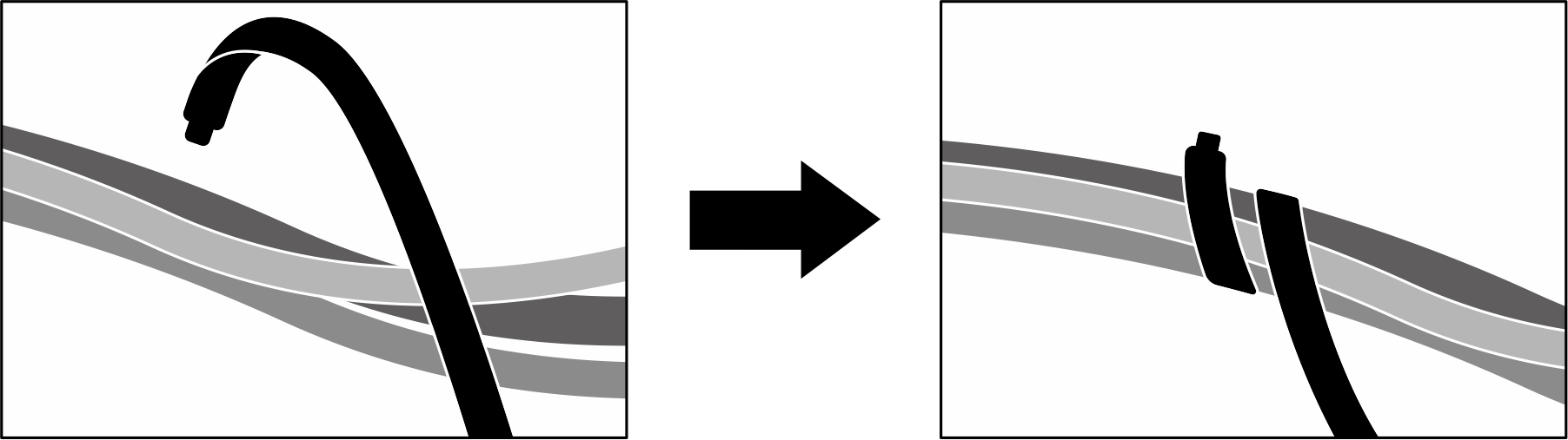
Teilen Sie die Kabel, die an der PCIe-Switch-Platine angeschlossen sind, in vier Bündel auf, und befestigen Sie sie mit Kabelbindern.
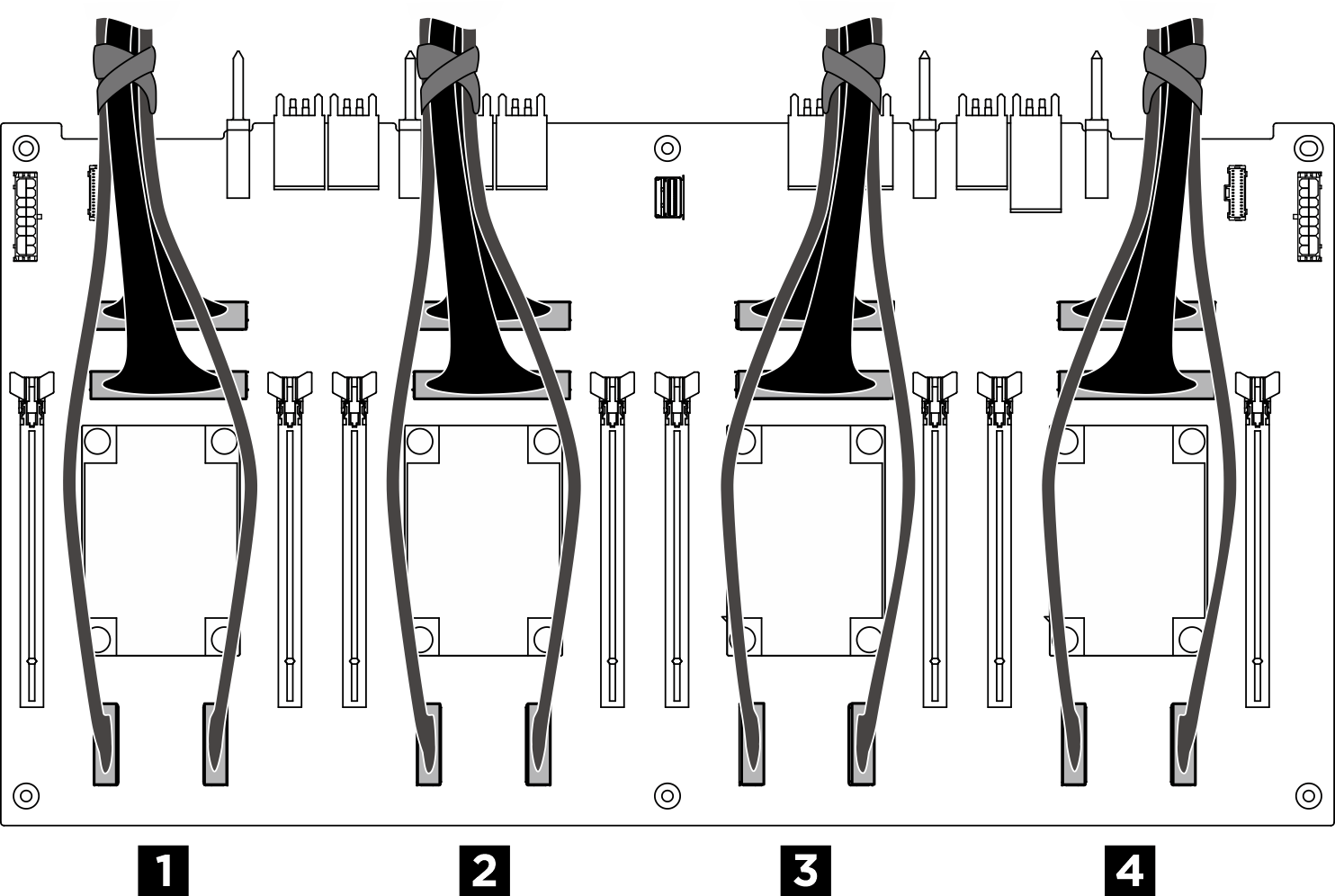
Abbildung 3. Sichern von Kabeln mit Kabelbindern
| Bündel | Kabel |
| 1 |
|
| 2 |
|
| 3 |
|
| 4 |
|
Feedback geben