System-board switches and jumpers
This section contains information regarding the system board switches and jumpers.
Figure 1. Location and description of switches and jumpers
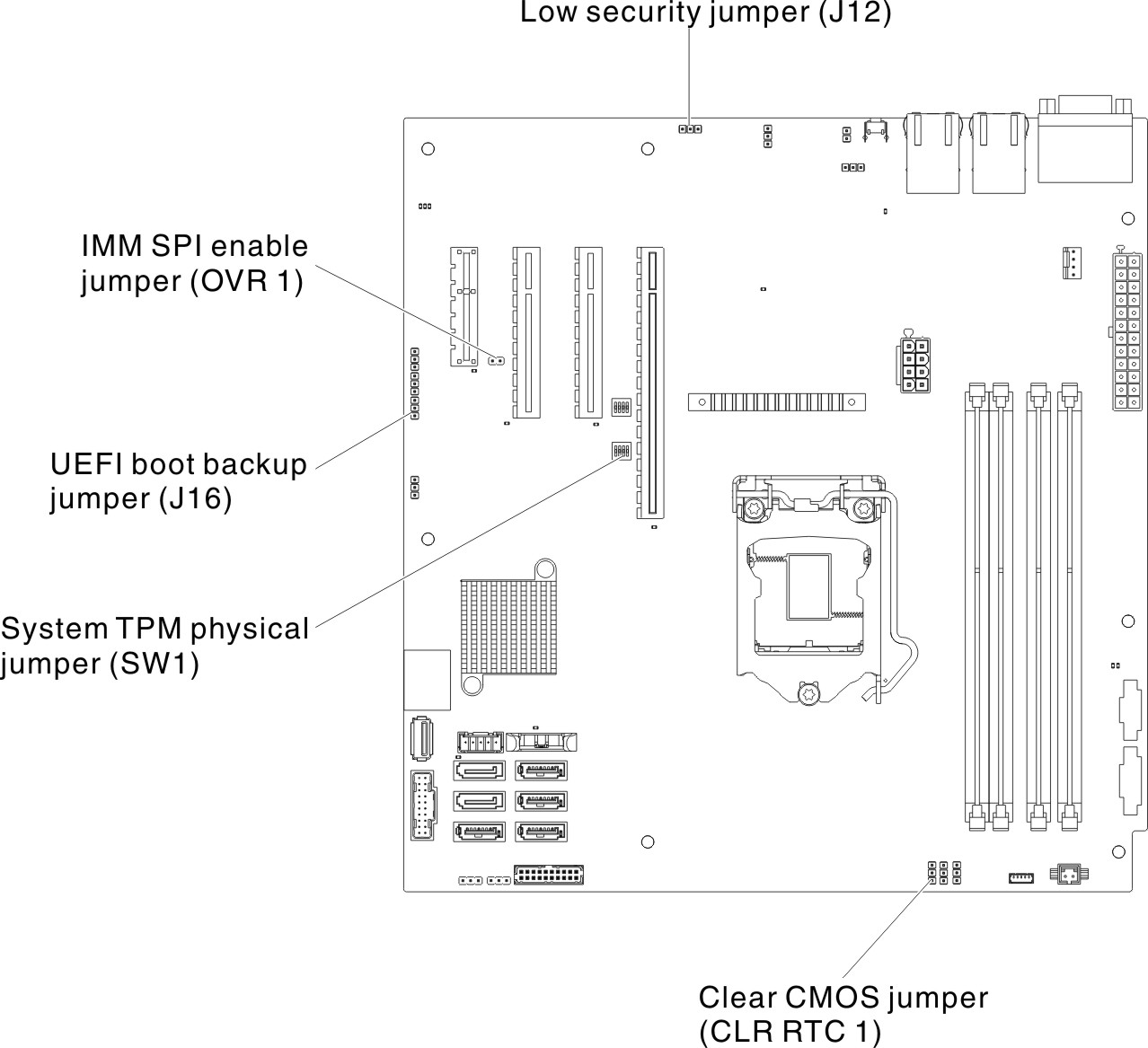
The following table describes the functions of switches and jumpers on the system board.
| Jumper number | Jumper name | Jumper setting |
|---|---|---|
| J12 | Low security jumper |
|
| OVR 1 | IMM SPI enable jumper |
|
| J16 | UEFI boot backup jumper |
|
| CLR RTC 1 | Clear CMOS jumper |
|
Note
| ||
Important
- Before you change any switch settings or move any jumpers, turn off the server; then, disconnect all power cords and external cables. Review the information in Safety, Installation guidelines, Handling static-sensitive devices, and Turning off the server.
- Any system-board switch or jumper blocks that are not shown in the illustrations in this document are reserved.
- If there is a clear protective sticker on the top of the switch blocks, you must remove and discard it to access the switches.
Give documentation feedback