PCI riser-card adapter expansion slot connectors
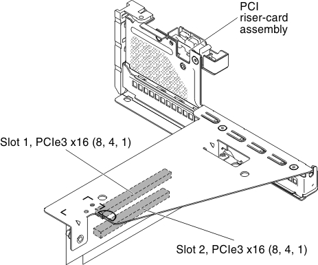
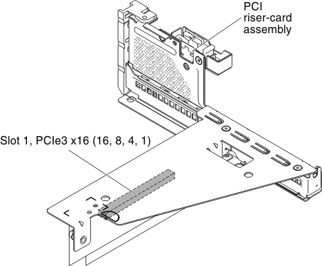
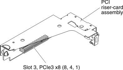
The following illustration shows the respective expansion slot connectors on the three different types of PCI riser card assemblies that the server is capable of supporting.
Note
The specifications of the following slot labeling is defined in the following format.
PCIe3 x aa (b, c, d, e)
where:
- aa = Physical connector link width
- b, c, d, e = Negotiable link width
PCI riser-card assembly 1
- Type 1Figure 1. PCI riser-card assembly 1 (Type 1)

- Type 2Figure 2. PCI riser-card assembly 1 (Type 2)

PCI riser-card assembly 2
Figure 3. PCI riser-card assembly 2 

Give documentation feedback