Installing a 4x 2.5-inch NVMe PCIe SSD upgrade kit

Use this information to install a 4x 2.5-inch NVMe PCIe SSD upgrade kit.

To order a 4x 2.5-inch NVMe PCIe SSD upgrade kit, contact your sales representative or reseller.

The 4x 2.5-inch NVMe PCIe SSD upgrade kit contains the following components:
  • Four signal cables
  • One power/configuration cable
  • One backplane assembly

One upgrade kit is supported in eight 2.5-inch-drive or sixteen 2.5-inch-drive models. The server must meet the following requirements:

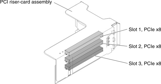
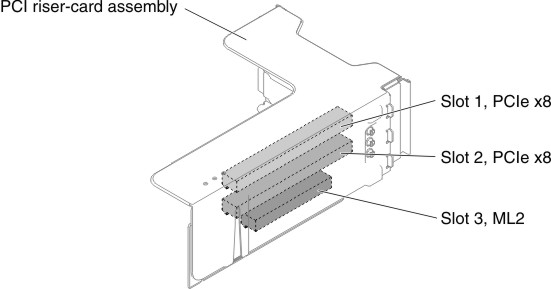
PCI riser card type in riser-card assembly 1PCI riser card type in riser-card assembly 2NVMe adapter installation sequence
Type 1
Type 1 PCI riser card
No limitation.

If microprocessor 2 is not installed, riser-card assembly 2 is not supported.

PCI slot 1, 2
Type 2
Type 2 PCI riser card
No limitation.

If microprocessor 2 is not installed, riser-card assembly 2 is not supported.

PCI slot 1, 2

To install the 4x 2.5-inch NVMe PCIe SSD upgrade kit in the server, complete the following steps.

  1. Read the safety information that begins on Safety and Installation guidelines.
  2. Turn off the server and peripheral devices and disconnect the power cords and all external cables, if necessary.
  3. Remove the cover (see Removing the top cover).
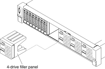
  4. Remove the two 4-drive filler panels according to your configuration.
    Figure 1. Filler panels
    Filler panels
  5. To obtain more working room, remove the fan cage (see Removing the fan cage assembly).
  6. Install the new backplanes. (See Replacing the 2.5-inch simple-swap backplate assembly/hot-swap hard disk drive backplane).
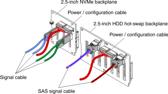
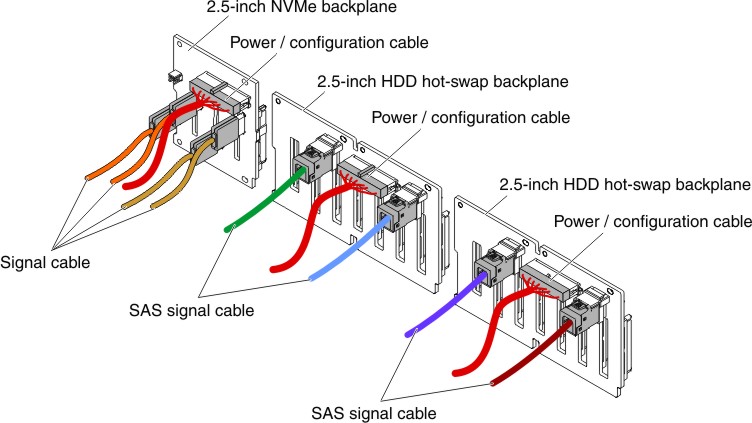
  7. Connect the power/configuration and signal cables to the backplane.
    • 8x 2.5-inch HDD + 4x 2.5-inch NVMe PCIe SSD
      Figure 2. Cable connections
      Cable connections
    • 16x 2.5-inch HDD + 4x 2.5-inch NVMe PCIe SSD
      Figure 3. Cable connections
      Cable connections
  8. Touch the static-protective package that contains the NVMe adapter to any unpainted metal surface on the server. Then, remove the NVMe adapter from the package.
  9. Remove the PCI riser-card assemblies. (see Removing a riser-card assembly).
  10. Install NVMe adapters in the connectors on the PCI riser card (see Replacing an adapter).
    Attention
    Incomplete insertion might cause damage to the server or the adapter.
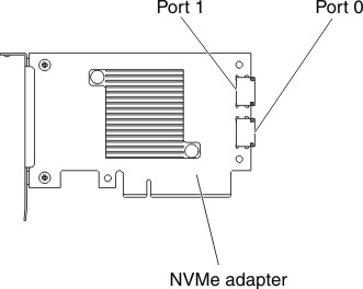
  11. Connect the four signal cables to the connectors on the NVMe adapter:
    Figure 4. NVMe adapter connectors
    NVMe adapter connectors
  12. Align and install the PCI riser-card assemblies in the server (see Replacing a riser-card assembly).
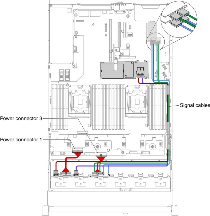
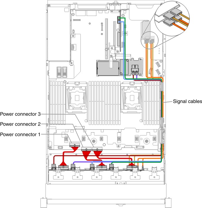
  13. Route the cables underneath the cable retention.
    • 8x 2.5-inch HDD + 4x 2.5-inch NVMe PCIe SSD
      Figure 5. Cable routing
      Cable routing
      Note
      1. For the power cable connection, the NVMe backplane can only connect to the power connector 3.
      2. There might be 3 or 4 power connectors on the system board depending on your configuration. However, this difference will not affect the cable routing. Follow the following illustrations to complete your cable routing.
    • 16x 2.5-inch HDD + 4x 2.5-inch NVMe PCIe SSD
      Figure 6. Cable routing
      Cable routing
      Note
      1. For the power cable connection, the NVMe backplane can only connect to the power connector 3.
      2. There might be 3 or 4 power connectors on the system board depending on your configuration. However, this difference will not affect the cable routing. Follow the following illustrations to complete your cable routing.
  14. If you removed the fan cage, install it back to the server. (See Replacing the fan cage assembly).
  15. Insert the hard disk drives and the fillers the rest of the way into the bays. (See Replacing a hot-swap hard disk drive).