Install a node to the DIN rail
Follow instructions in this section to install a node to the DIN rail.
About this task
S002
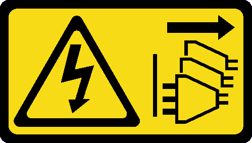
CAUTION
The power-control button on the device and the power switch on the power supply do not turn off the electrical current supplied to the device. The device also might have more than one power cord. To remove all electrical current from the device, ensure that all power cords are disconnected from the power source.
Attention
Read Installation Guidelines and Safety inspection checklist to ensure that you work safely.
Power off the server and peripheral devices and disconnect the power cords and all external cables. See Power off the server.
Reserve 500 mm of clearance in front of the node for installation/removal procedure.
Note
Depending on the model, your server might look slightly different from the illustration.
Procedure
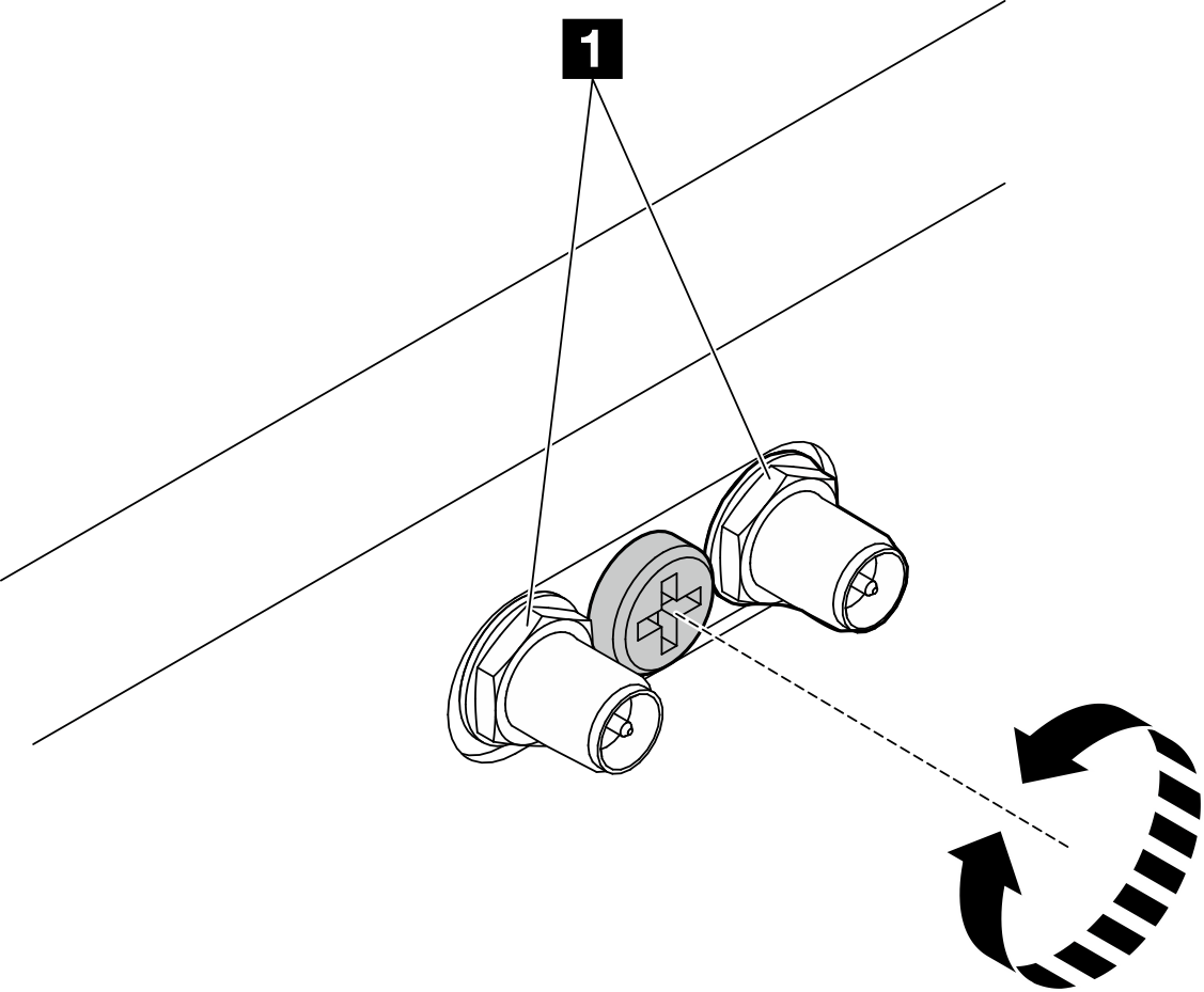
- If applicable, turn the screw between the two SMA connectors clockwise to shorten the connectors into the chassis.NoteMake sure that the SMA connectors are shortened into the chassis; if the SMA connectors are extended and out of the chassis, the node can not be installed successfully.Figure 1. Shortening the SMA connectors
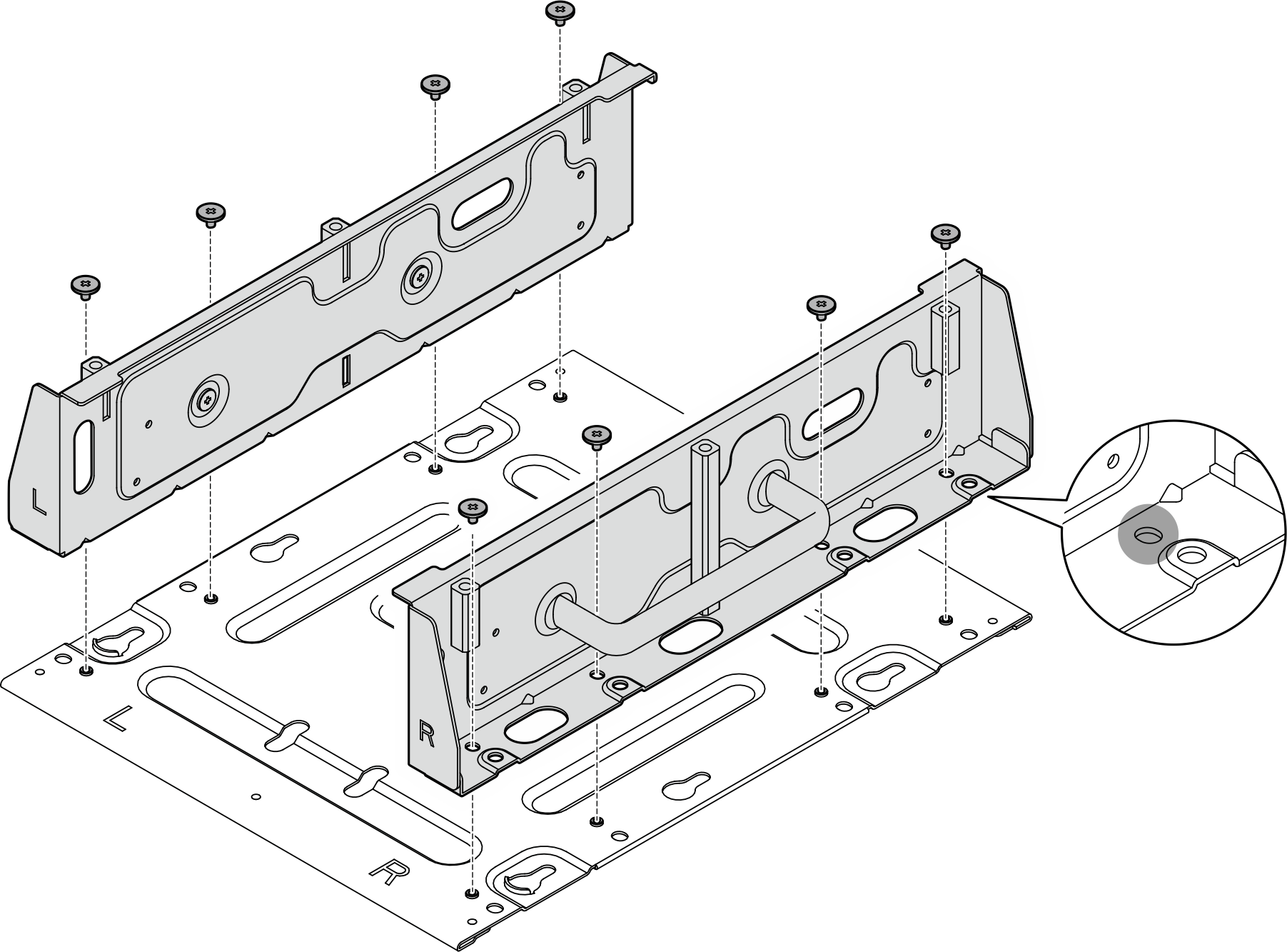
- Loosen the eight screws that secure the two side brackets (four for each side bracket) to disassemble the node bracket.Figure 2. Disassembling the node bracket
- Depending on the model, fasten four screws or thumbscrews to secure one side bracket to the node; then, repeat the procedure to the other side bracket.NoteThere are “L” and “R” logos marked on the front of side brackets which represent the left bracket and the right bracket (viewed from the front of the node). Make sure to install the brackets with correct orientation shown in the illustration.Figure 3. Installing the side brackets with screws
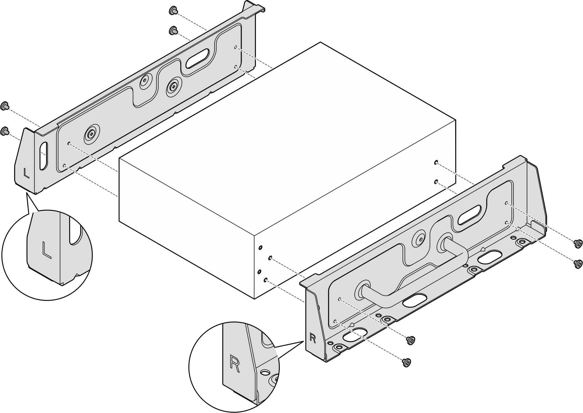 Figure 4. Installing the side brackets with thumbscrews
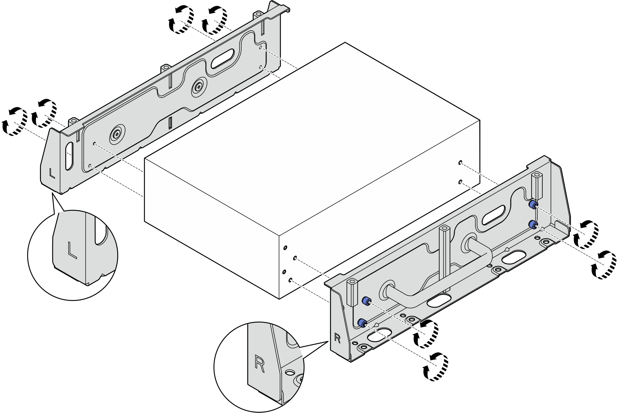
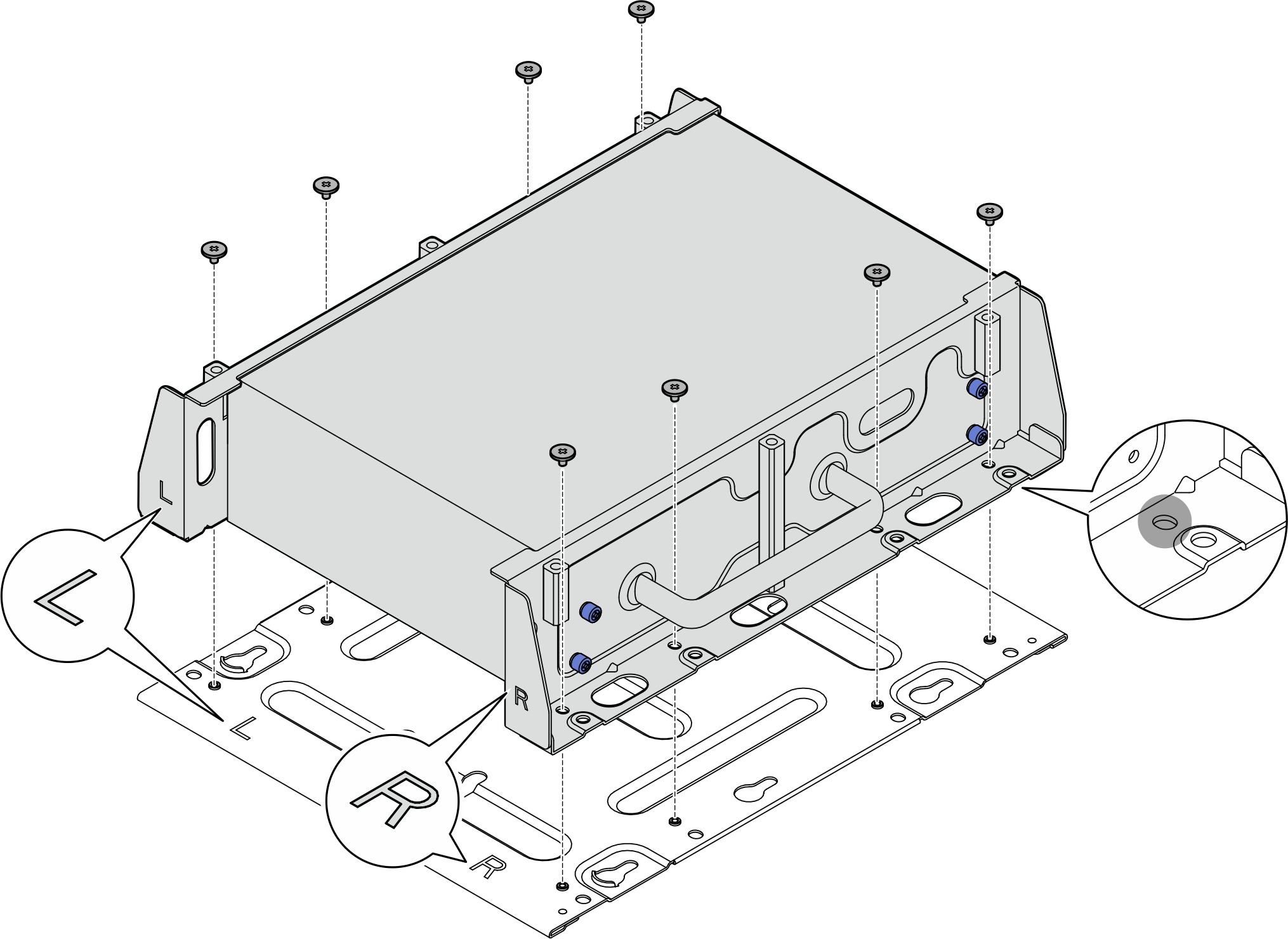
- Secure the bottom plate to the node with eight screws (four for each side).NoteMake sure to fasten the screws to the screw holes close to the node.Figure 5. Installing the bottom plate
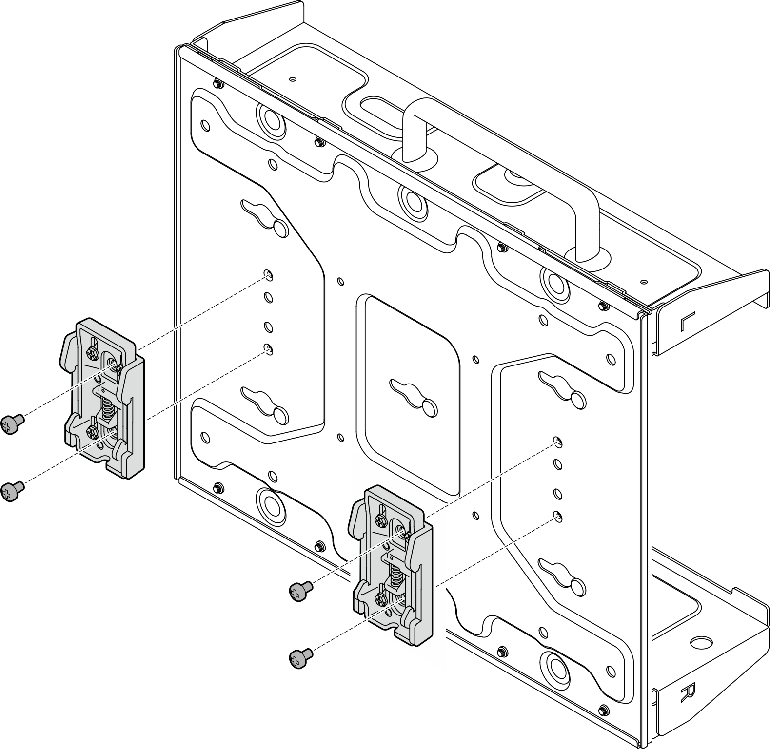
- Secure the DIN rail clips to the node sleeve with two screws for each clip.Figure 6. Installing the DIN rail clips
- Mount the node sleeve to the DIN rail.
 Hook the top side of DIN rail clips onto the rail at an angle.
 Pivot the node sleeve toward the DIN rail, and ensure the DIN rail clips are securely seated.
Figure 7. Installing the node sleeve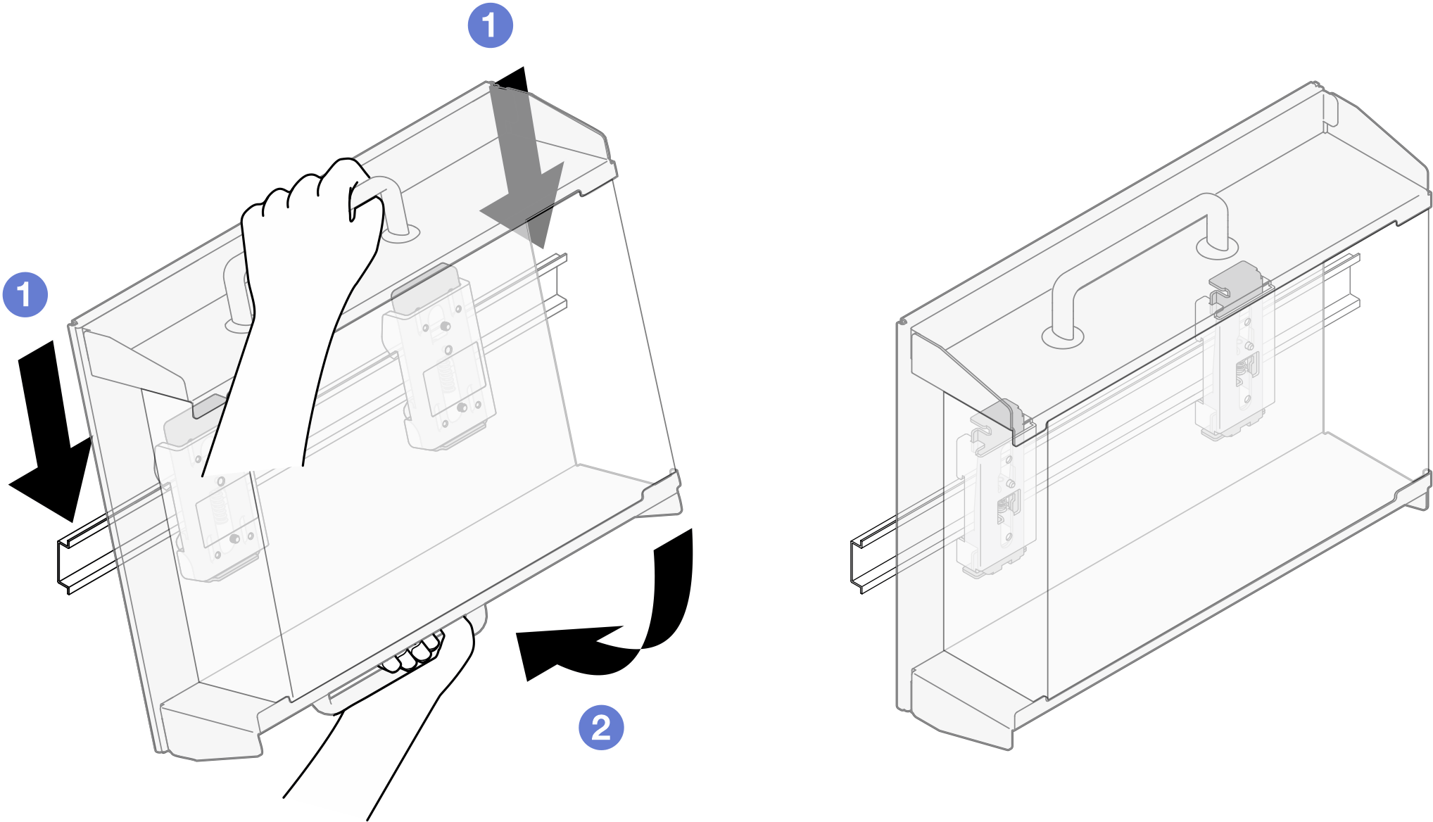
- (Optional) If necessary, install the security bezel.NoteWhen the security bezel is installed, the front operator panel and USB Type-C connectors are not accessible.
- Insert the tab of security bezel into the slot; then, pivot the security bezel toward the node sleeve until the other side of security bezel clicks into place.NoteMake sure that the external cables in front of the node go through the corresponding openings of the security bezel.
- Lock the security bezel with the key, and store the key for future use.
Figure 8. Installing the security bezel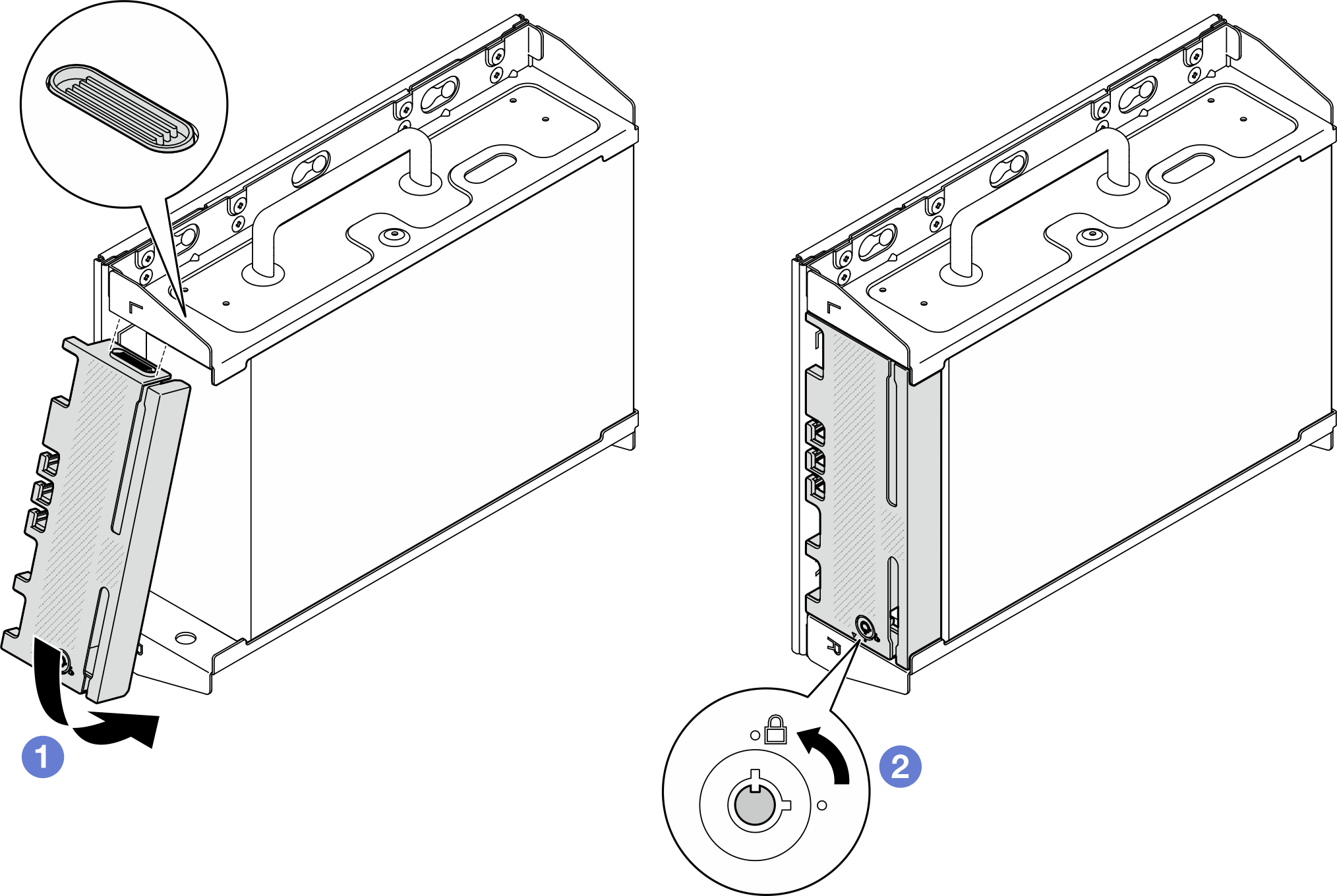
Give documentation feedback