Remove a memory module
Follow instructions in this section to remove a memory module.
About this task
Read Installation Guidelines and Safety inspection checklist to ensure that you work safely.
Power off the server and peripheral devices and disconnect the power cords and all external cables. See Power off the server.
If the node is installed in an enclosure or mounted, remove the node from the enclosure or mount. See Configuration guide.
- Memory modules are sensitive to static discharge and require special handling. Refer to the standard guidelines for Handling static-sensitive devices.
Always wear an electrostatic-discharge strap when removing or installing memory modules. Electrostatic-discharge gloves can also be used.
Never hold two or more memory modules together so that they do not touch each other. Do not stack memory modules directly on top of each other during storage.
Never touch the gold memory module connector contacts or allow these contacts to touch the outside of the memory module connector housing.
Handle memory modules with care: never bend, twist, or drop a memory module.
Do not use any metal tools (such as jigs or clamps) to handle the memory modules, because the rigid metals may damage the memory modules.
Do not insert memory modules while holding packages or passive components, which can cause package cracks or detachment of passive components by the high insertion force.
Procedure
- Locate the memory module to be removed on the system board.Figure 1. Memory modules and processor layout
 ImportantBefore removing DIMM 1, remove DIMM 2 first.
 - Open the retaining clip with a memory module tool.Attention
- Due to space constraints, use a memory module tool to open the retaining clips. Do not use pencils or other fragile tools. When you received your server, the memory module tool is in the material box.
- To avoid breaking the retaining clips or damaging the memory module slots, handle the clips gently.
 Place the tip of the tool in the recess on the top of the retaining clip.
 Carefully rotate the retaining clip away from the DIMM slot to disengage the memory module. One end of the module will be slightly higher than the other.
Figure 2. Opening retaining clip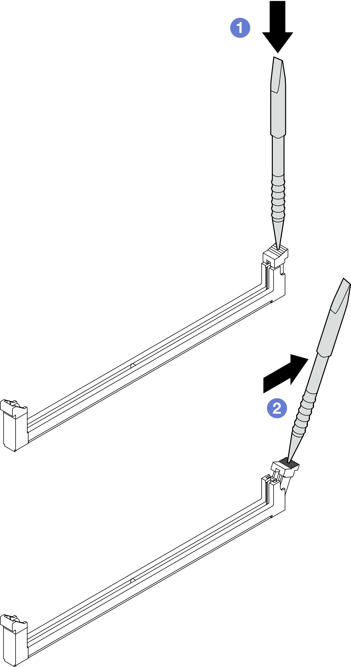
- Remove the memory module.
- Lift the higher side of the memory module up with the tool, and hold the memory module.
- Carefully lift the memory module out of the slot.
Figure 3. Removing memory module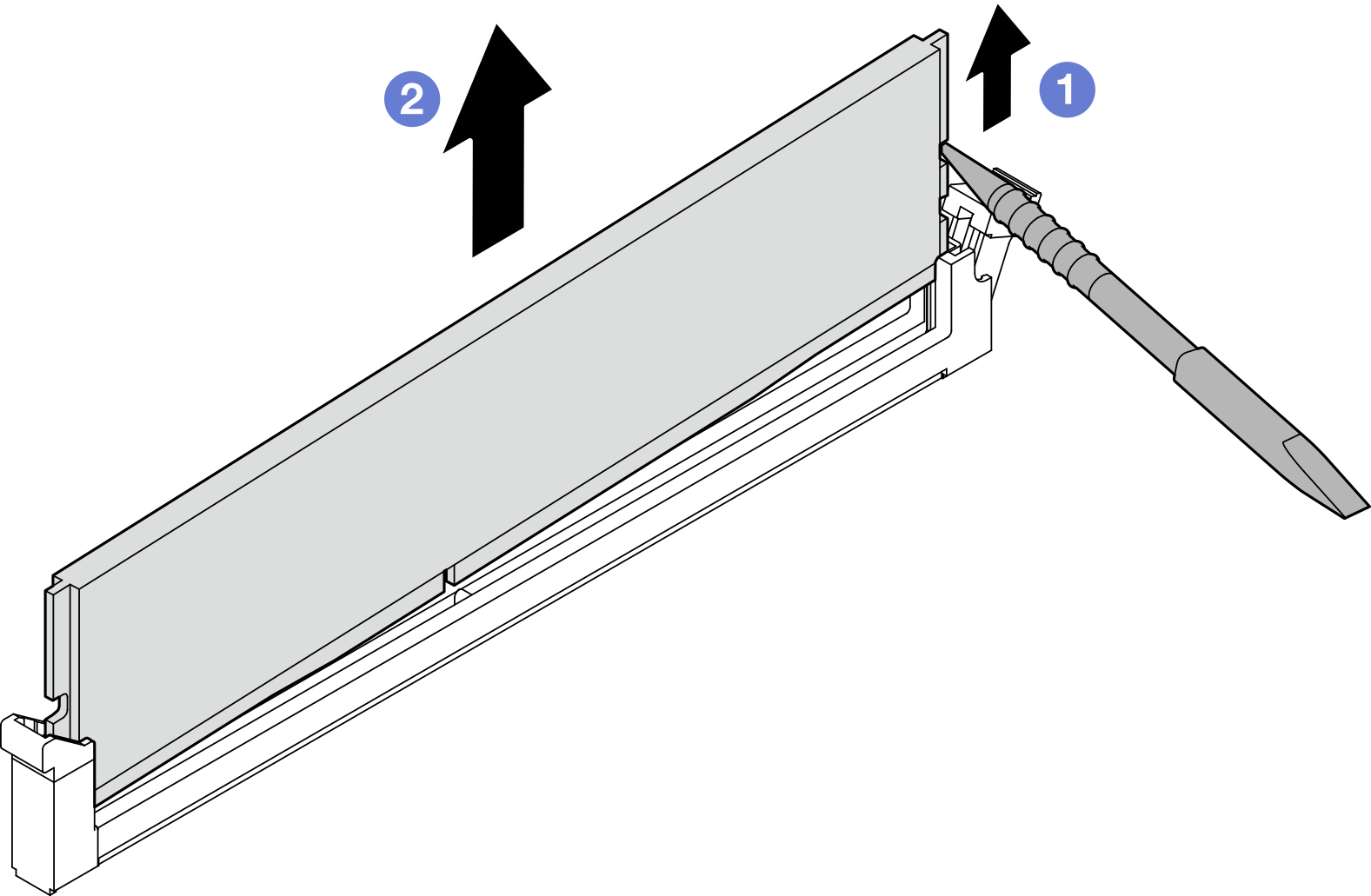 Attention
When removing a memory module from DIMM slot 1, to avoid the memory module touching nearby components, DO NOT lift the memory module straight up. Touching nearby components might cause damage to the memory module.

Store the memory module tool for future use.
Install a replacement unit. See Install a memory module.
If you are instructed to return the component or optional device, follow all packaging instructions, and use any packaging materials for shipping that are supplied to you.
Demo Video