Remove a node from the wall or the ceiling
Follow instructions in this section to remove a node from the wall or the ceiling.
About this task
Attention
Read Installation Guidelines and Safety inspection checklist to ensure that you work safely.
Reserve 500 mm of clearance in front of the node for installation/removal procedure.
Important
This task must be operated by trained technicians.
Note
Depending on the model, your server might look slightly different from the illustration.
Procedure
- If applicable, remove the security bezel.
 Unlock the security bezel with the key.
 Press the tab to disengage the security bezel.
 Pivot the security bezel outward, and remove the security bezel.
Figure 1. Removing the security bezel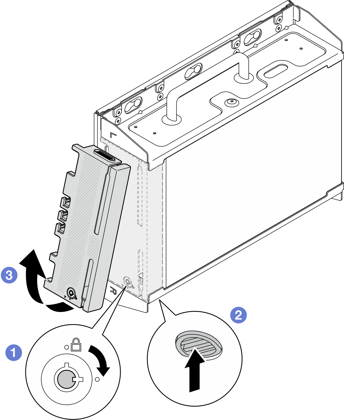
- Power off the server and peripheral devices and disconnect the power cords and all external cables. See Power off the server.S002
 CAUTIONThe power-control button on the device and the power switch on the power supply do not turn off the electrical current supplied to the device. The device also might have more than one power cord. To remove all electrical current from the device, ensure that all power cords are disconnected from the power source.
 - Remove the node bracket from the wall-mount plate.
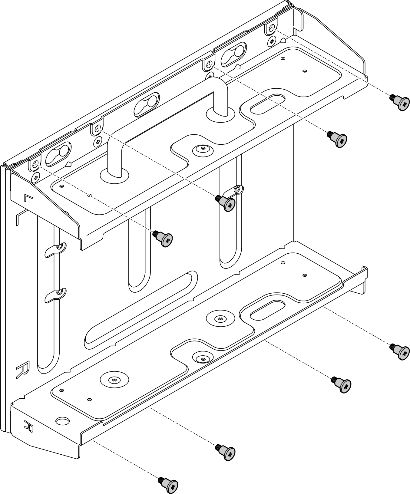
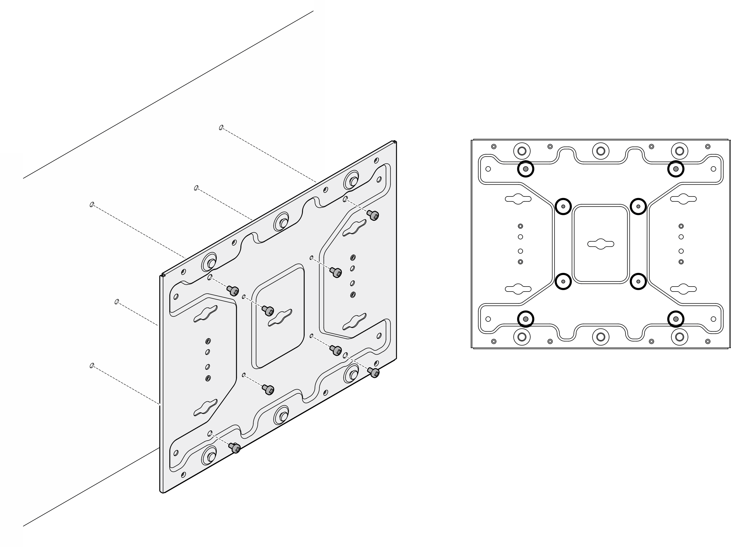
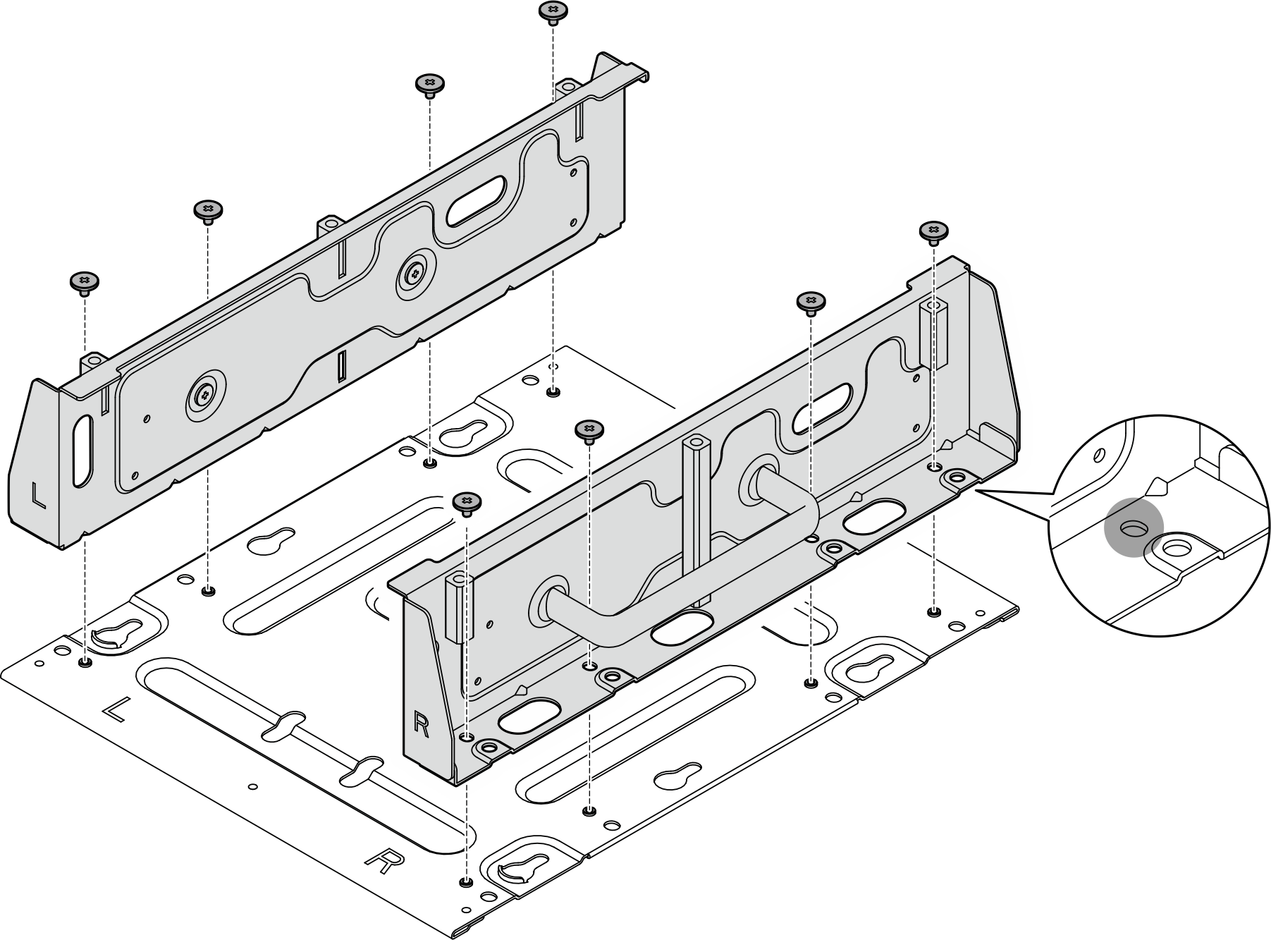
- Loosen the eight screws that secure the node bracket.Figure 2. Removing the node bracket
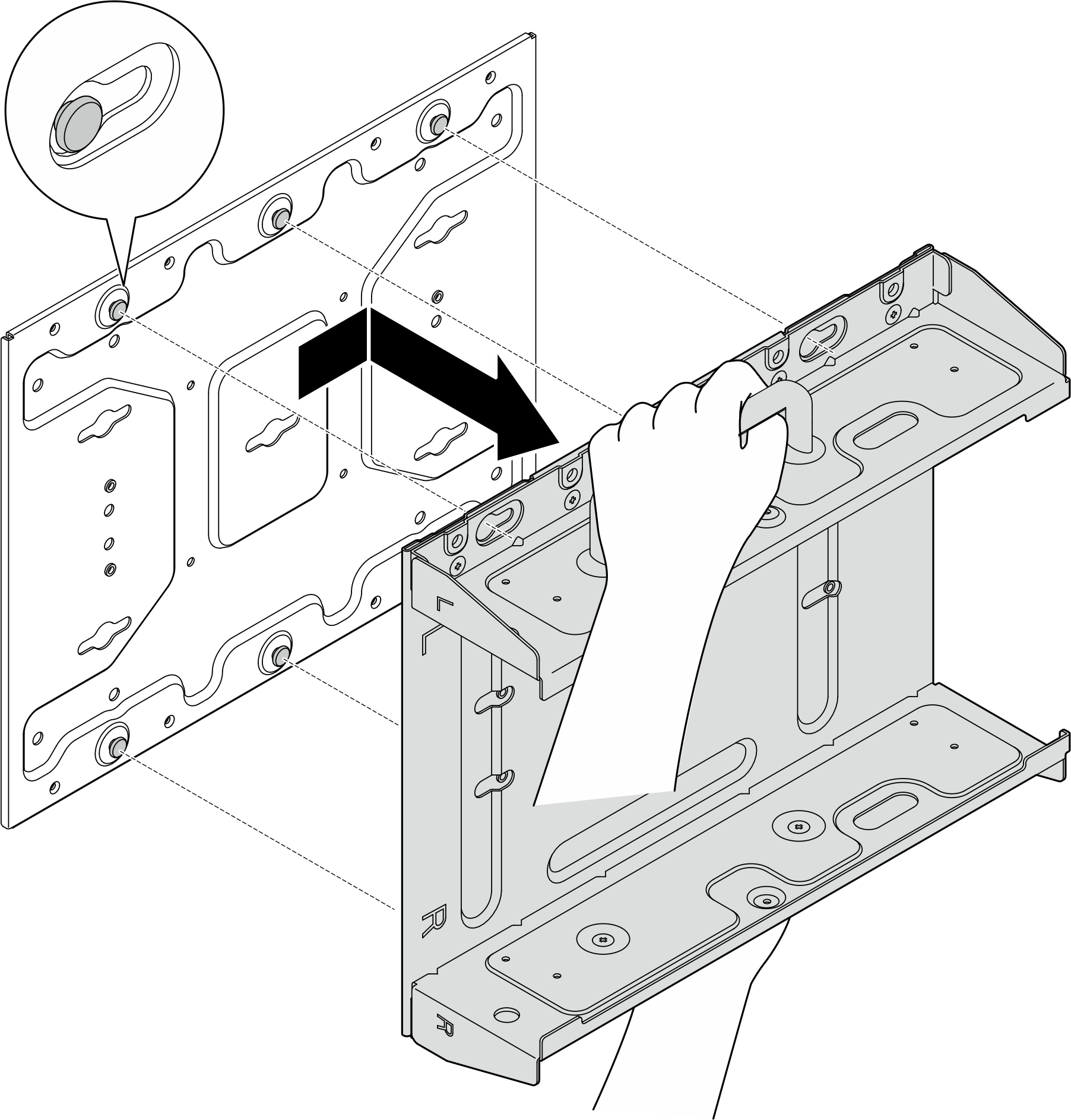
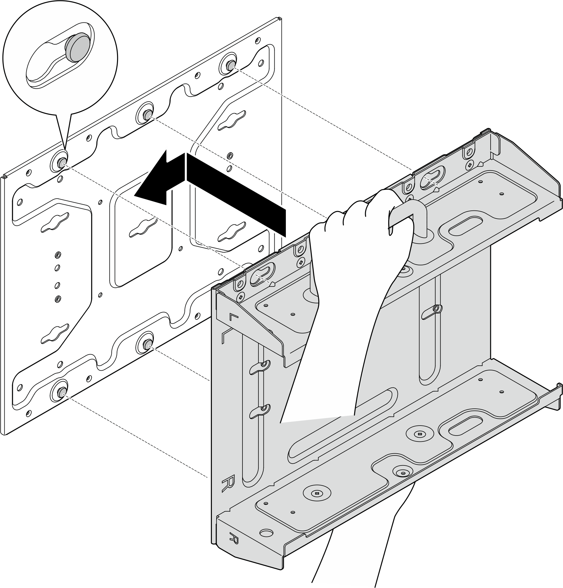
- Slide the node bracket until the guide pins on the wall-mount plate are seated in the large opening of the keyhole; then, remove the node bracket from the wall-mount plate.Figure 3. Removing the node bracket
- Loosen the eight screws that secure the node bracket.
- Loosen the four M4 screws and four M6 screws that secure the wall-mount plate; then, remove the wall-mount plate from the wall.Figure 4. Removing the wall-mount plate
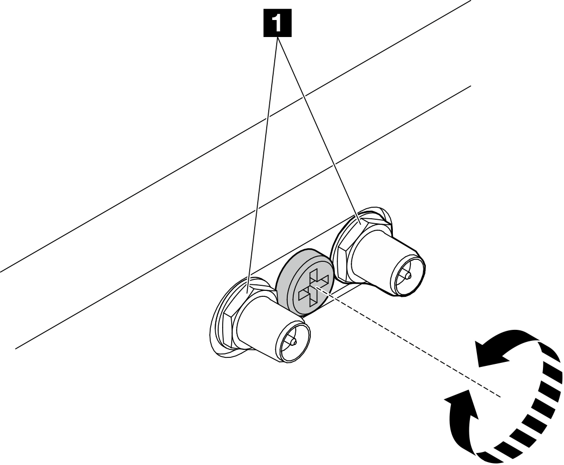
- If applicable, turn the screw between the two SMA connectors clockwise to shorten the connectors into the chassis.NoteMake sure that the SMA connectors are shortened into the chassis; if the SMA connectors are extended and out of the chassis, the node can not be removed successfully.Figure 5. Shortening the SMA connectors
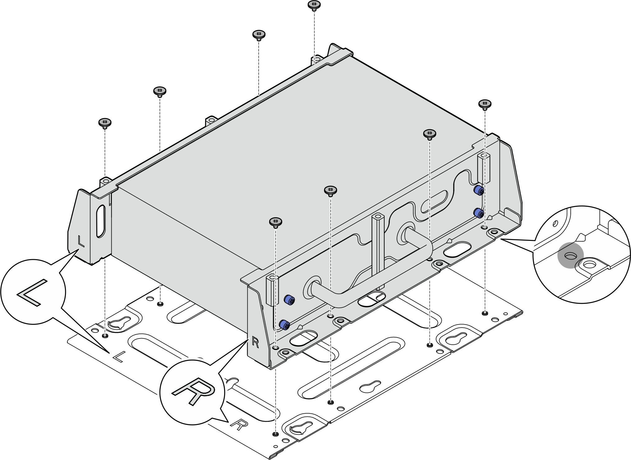
- Loosen the eight screws (four for each side) that secure the bottom plate to remove the plate from the node.Figure 6. Removing the bottom plate
- Depending on the model, loosen the four screws or thumbscrews that secure the side bracket to remove the bracket from the node; then, repeat the procedure to the other bracket.Figure 7. Loosening screws to remove the side brackets
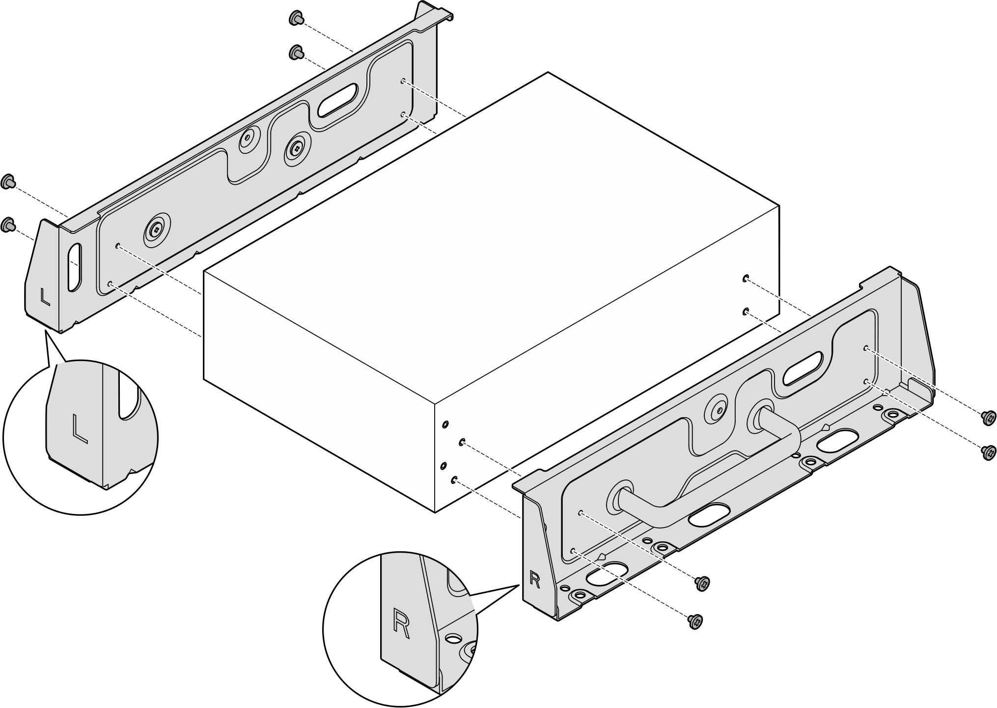 Figure 8. Loosening thumbscrews to remove the side brackets
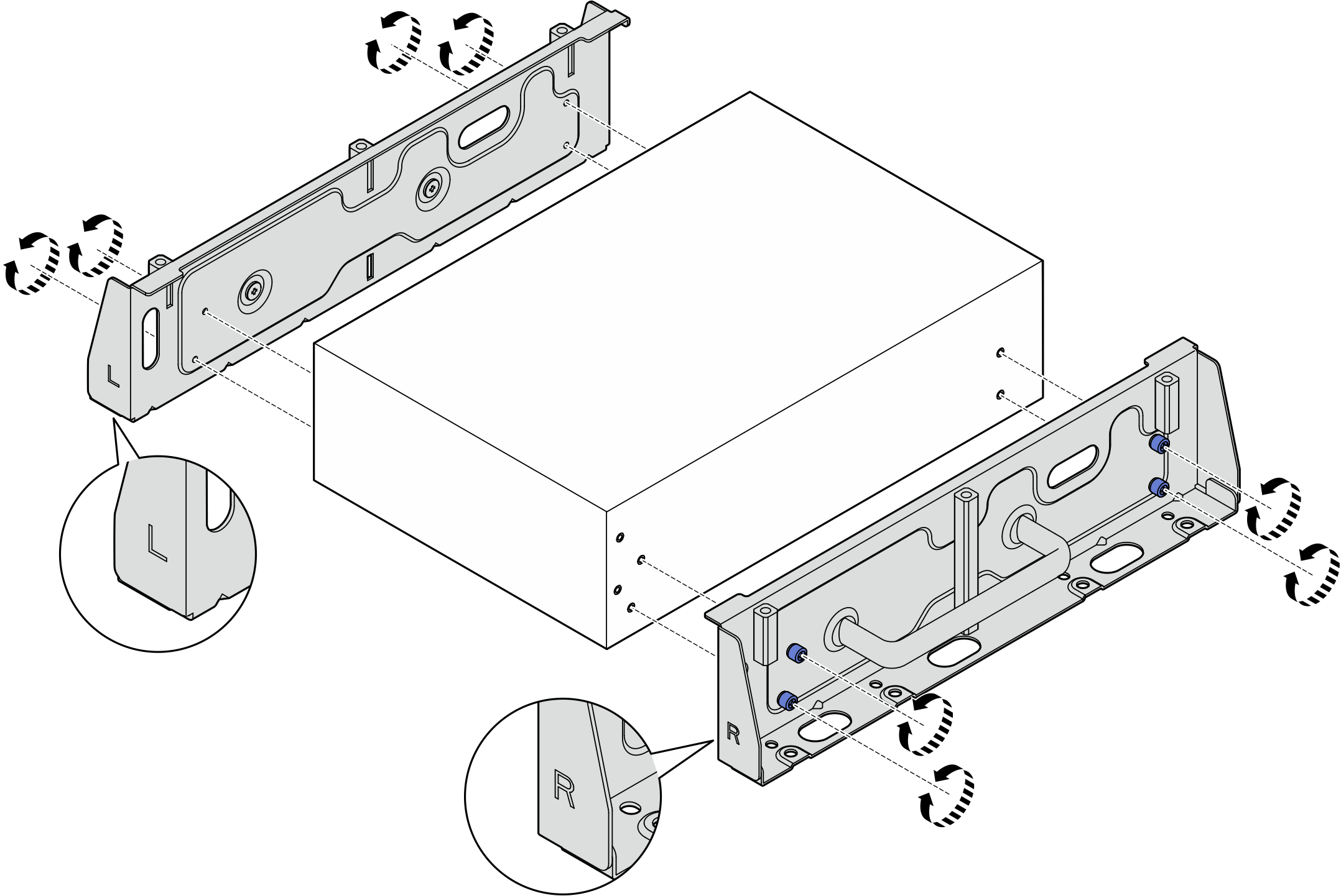
- If necessary, secure the two side brackets to the bottom plate with eight screws (four for each bracket) to assemble the node bracket.NoteMake sure to align the “L” and “R” logos on the front of side brackets with the logos on the bottom plate.Figure 9. Assembling the node sleeve
- If necessary, combine the node bracket with the wall-mount plate.
- Push the node bracket toward the wall-mount plate; then, slide the node bracket until the guide pins are seated in the small opening of keyholes.Figure 10. Assembling the node sleeve
- Secure the node bracket with eight screws.Figure 11. Assembling the node sleeve
- Push the node bracket toward the wall-mount plate; then, slide the node bracket until the guide pins are seated in the small opening of keyholes.
After this task is completed
To reinstall the node to the wall, see Install a node to the wall or the ceiling.
Give documentation feedback