Install a node to the wall or the ceiling
Follow instructions in this section to install a node to the wall or the ceiling.
About this task
Read Installation Guidelines and Safety inspection checklist to ensure that you work safely.
Power off the server and peripheral devices and disconnect the power cords and all external cables. See Power off the server.
Reserve 500 mm of clearance in front of the node for installation/removal procedure.
The maximal weight of the SE360 V2 node with node sleeve is 9.54 KG (21.03 lbs). For safe installation, the wall to mount the node must be able to support 4 times of the weight, 38.16 KG (84.12 lbs). If not, the surface must be reinforced to meet this standard.
Avoid existing in-wall utilities, for example, plumbing, natural gas, or electrical input.
Procedure
- The wall mount configuration requires four M4 screws and four M6 screws. Prepare screws and related parts for this task.NoteThe appropriate length of the screw base should be assessed by qualified professionals.
Table 1. Max screw size for the inner four M4 screws 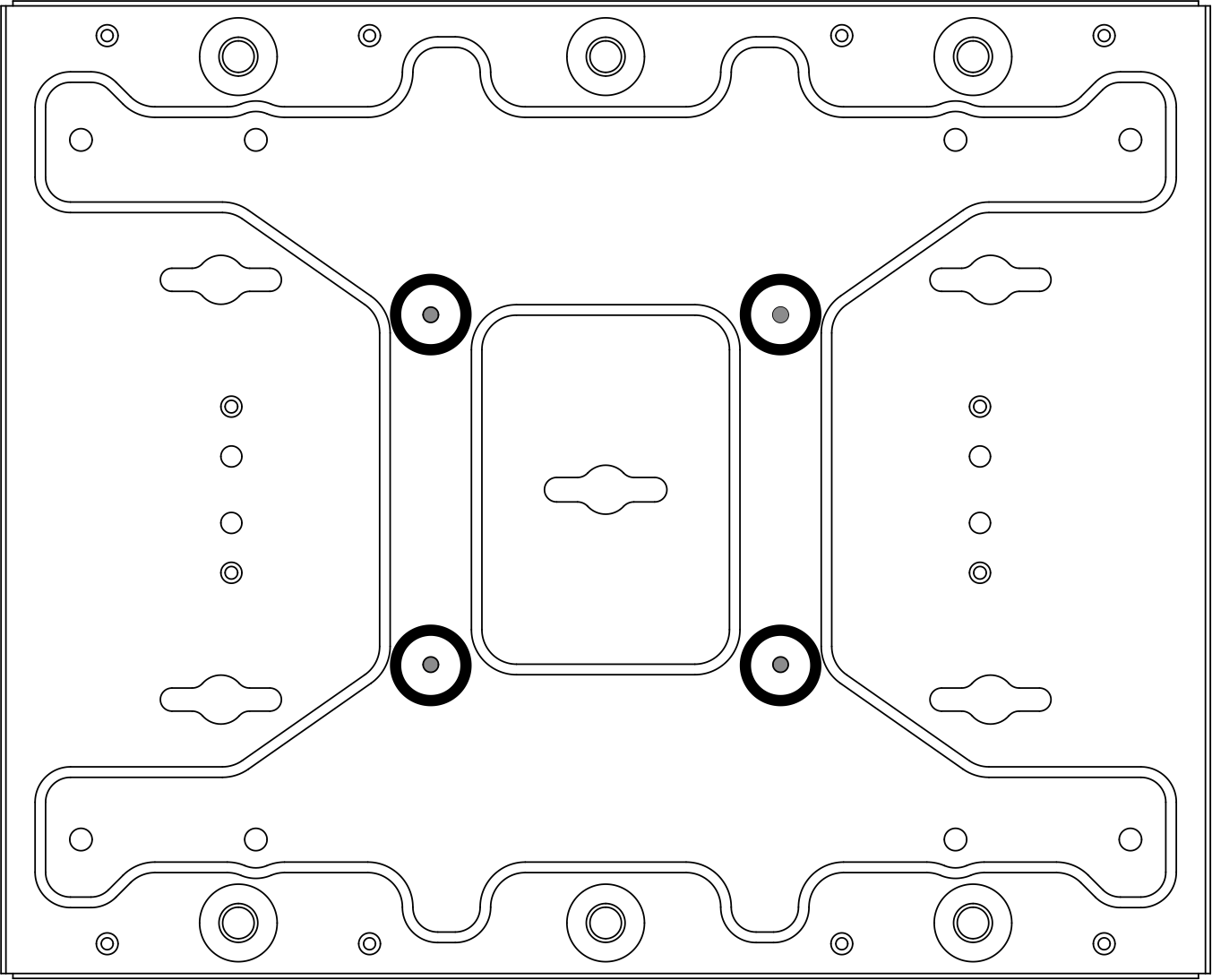
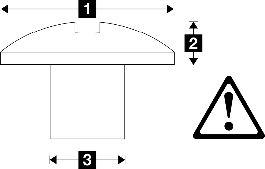
1 Ø10 mm 2 3 mm 3 4 mm Table 2. Screw size for the outer four M6 screws 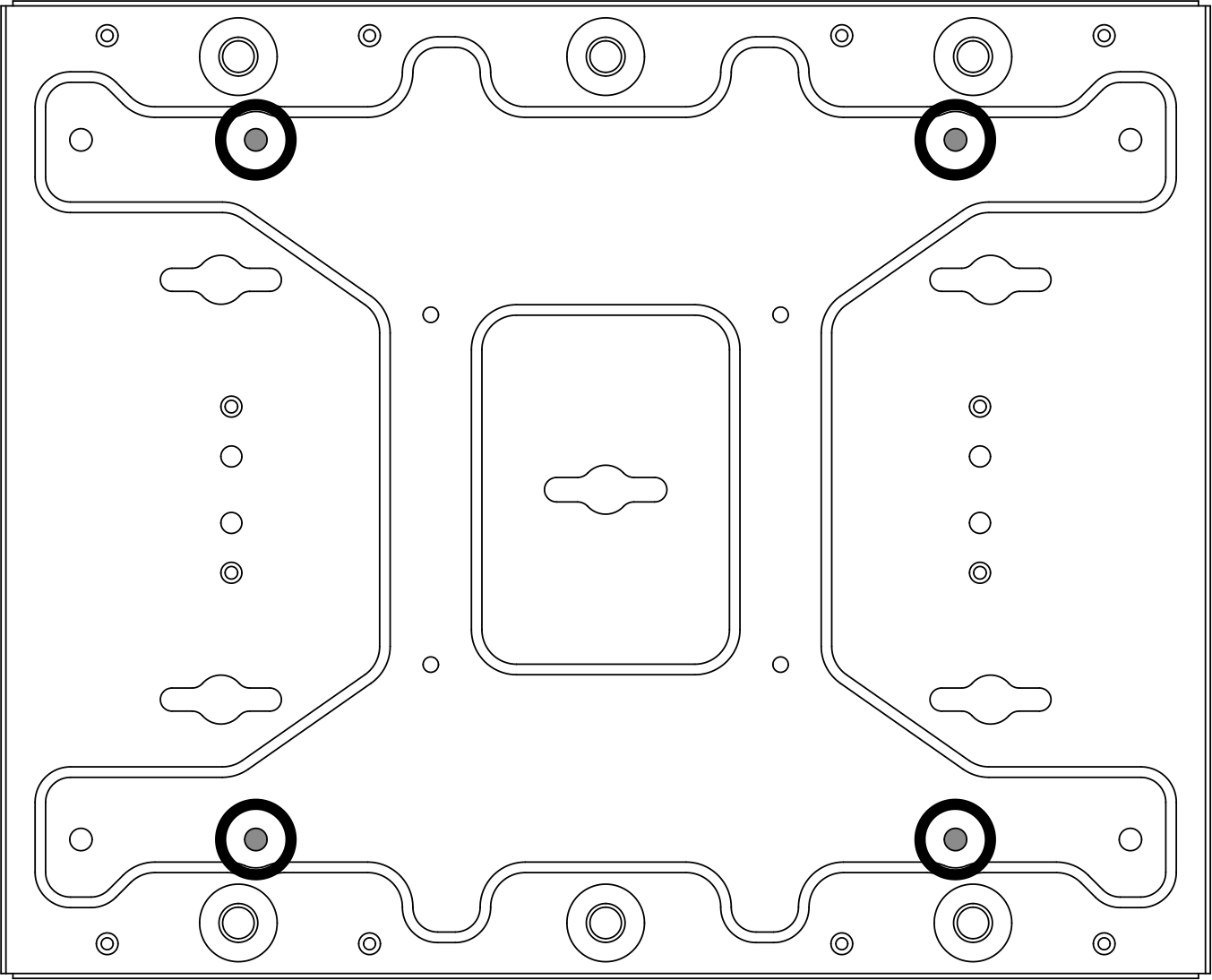
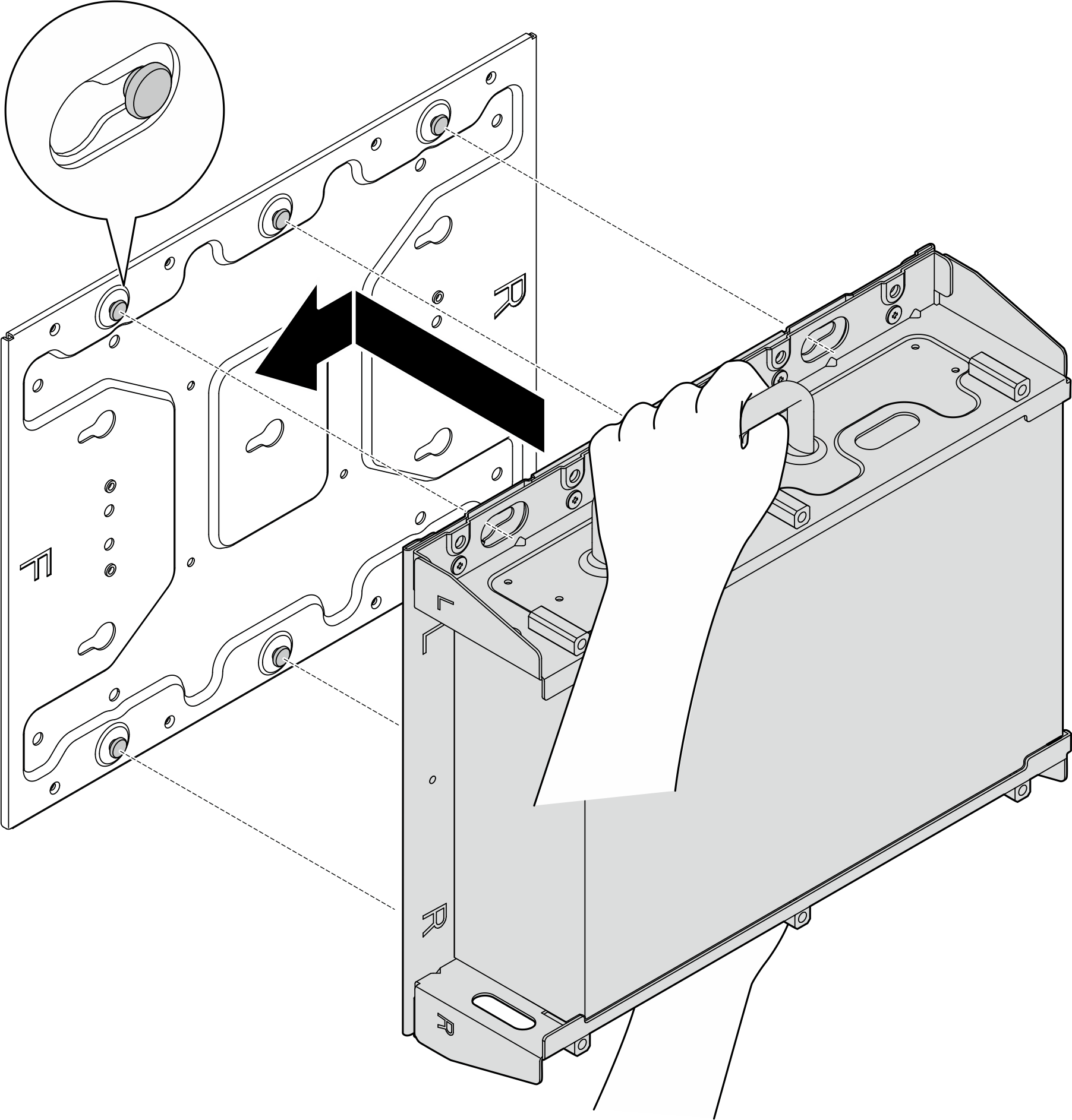
1 Max: Ø14 mm 2 Max: 3.4 mm 3 4-6 mm - Separate the node bracket from the wall-mount plate.
- Loosen the eight screws that secure the node bracket.
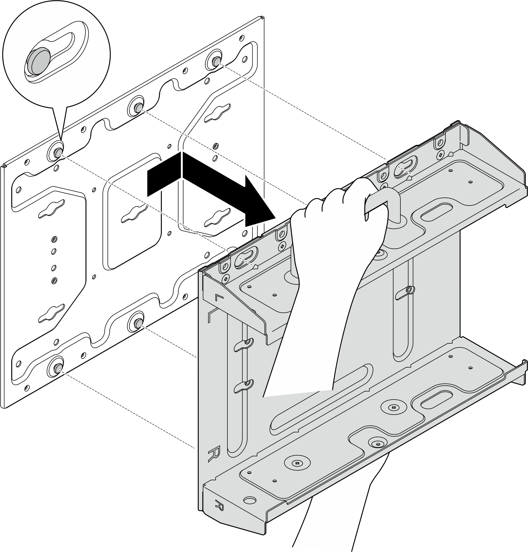
- Slide the node bracket until the guide pins on the wall-mount plate are seated in the large opening of the keyhole; then, remove the node bracket from the wall-mount plate.Figure 1. Separating the node bracket
- Loosen the eight screws that secure the node bracket.
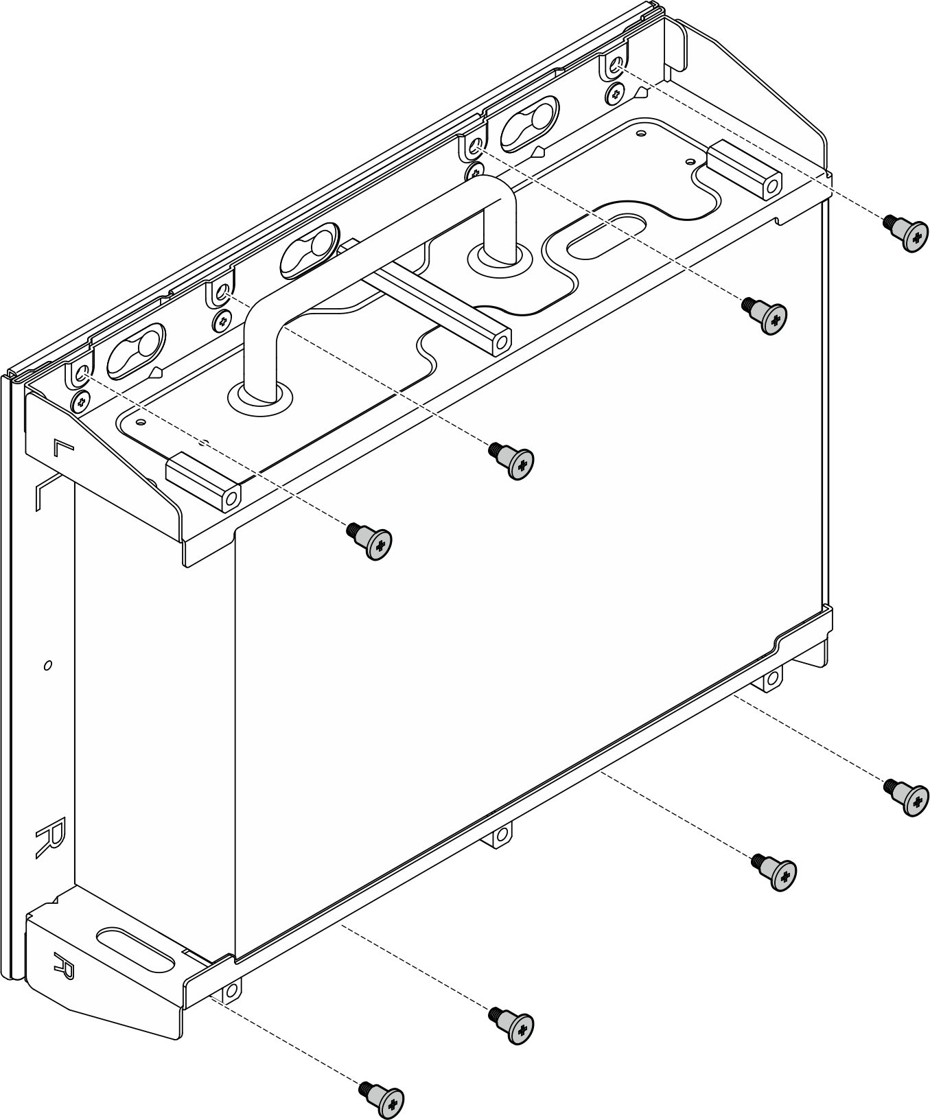
- Loosen the eight screws that secure the two side brackets (four for each side bracket) to disassemble the node bracket.Figure 2. Disassembling the node bracket
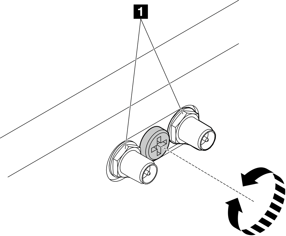
- If applicable, turn the screw between the two SMA connectors clockwise to shorten the connectors into the chassis.NoteMake sure that the SMA connectors are shortened into the chassis; if the SMA connectors are extended and out of the chassis, the node can not be installed successfully.Figure 3. Shortening the SMA connectors
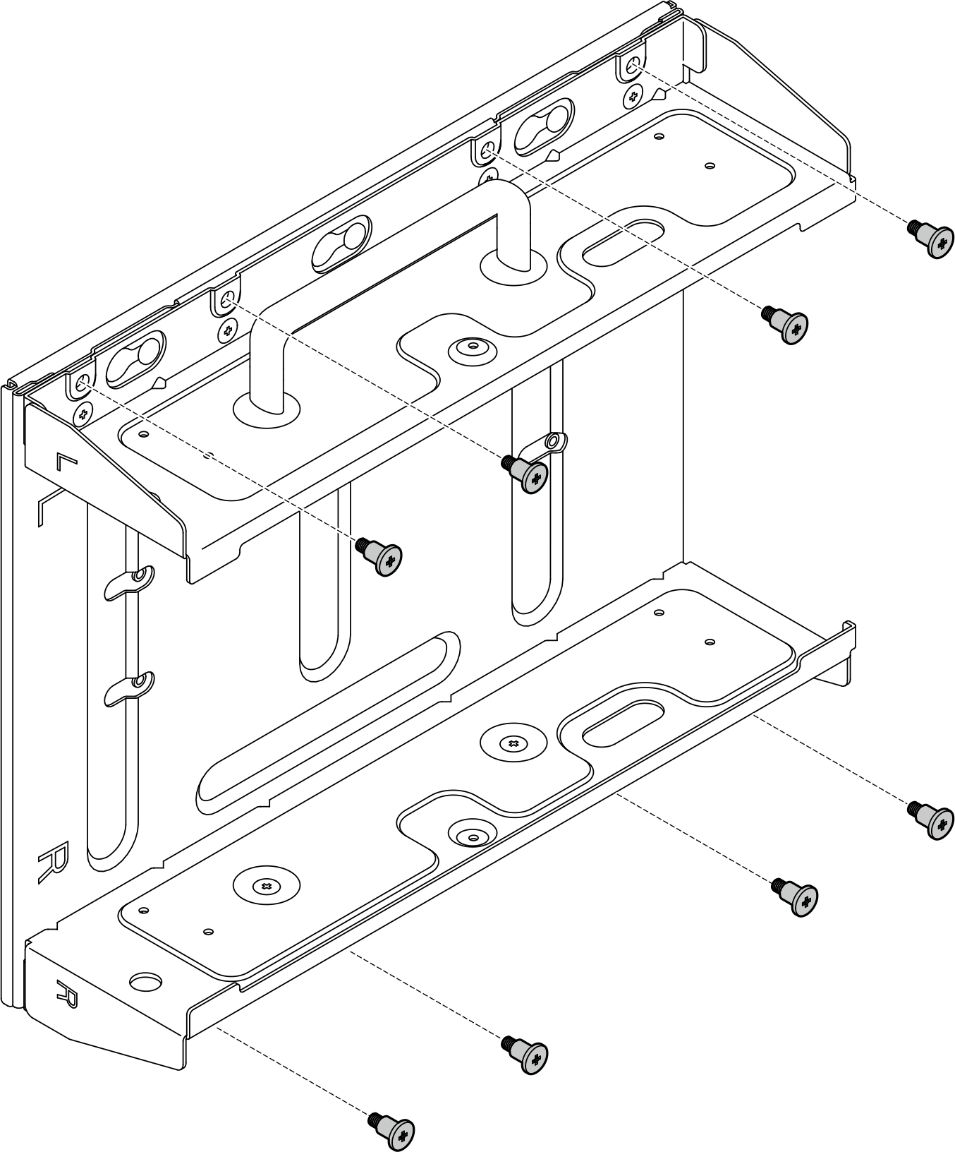
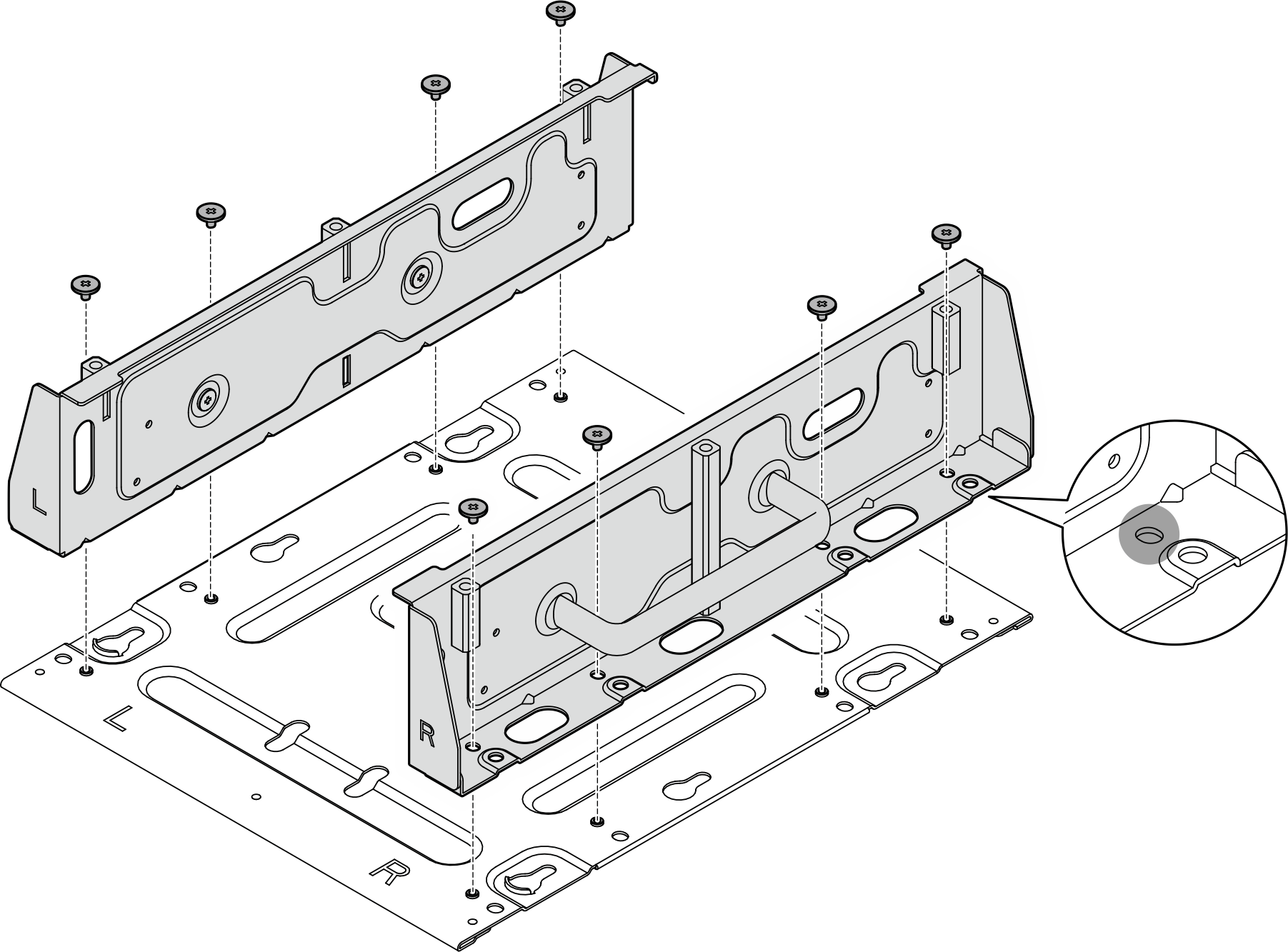
- Depending on the model, fasten four screws or thumbscrews to secure one side bracket to the node; then, repeat the procedure to the other side bracket.NoteThere are “L” and “R” logos marked on the front of side brackets which represent the left bracket and the right bracket (viewed from the front of the node). Make sure to install the brackets with correct orientation shown in the illustration.Figure 4. Installing the side brackets with screws
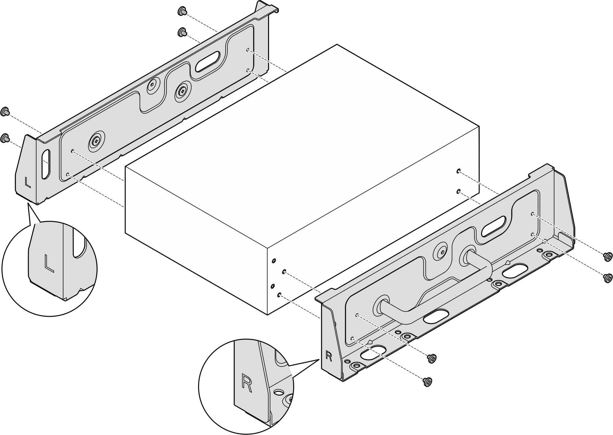 Figure 5. Installing the side brackets with thumbscrews
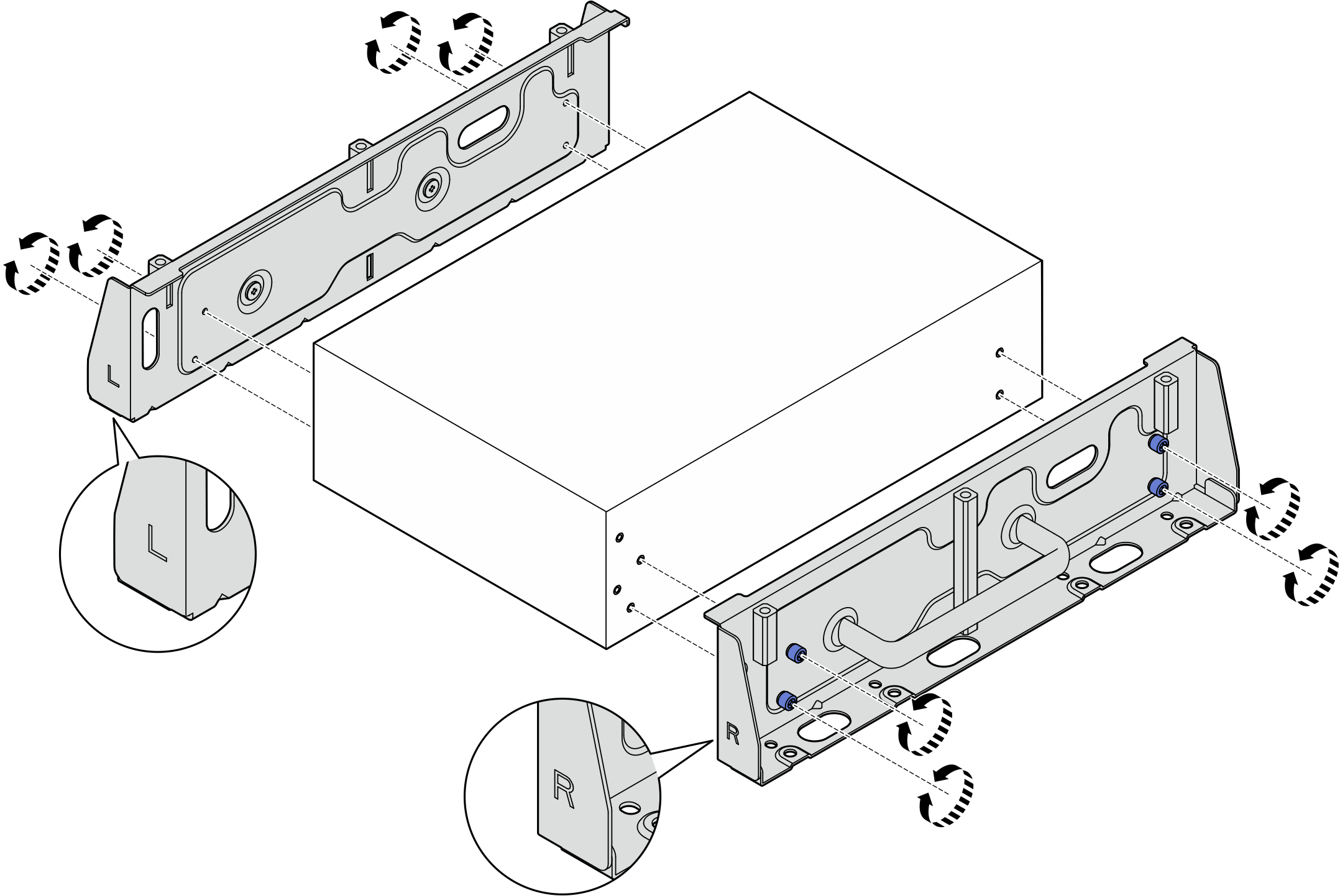
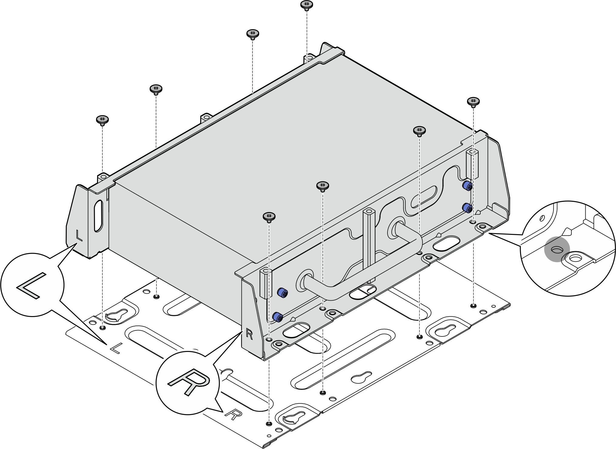
- Secure the bottom plate to the node with eight screws (four for each side).NoteMake sure to fasten the screws to the screw holes close to the node.Figure 6. Installing the bottom plate
- (Optional) To mount the node on a flat wall with no screw holes, drill eight screw holes on the wall if necessary.
- Press the wall-mount plate against the mounting location.
- Mark the locations of screw holes with a pencil.
- Drill eight screw holes as marked.
Figure 7. Locations of screw holes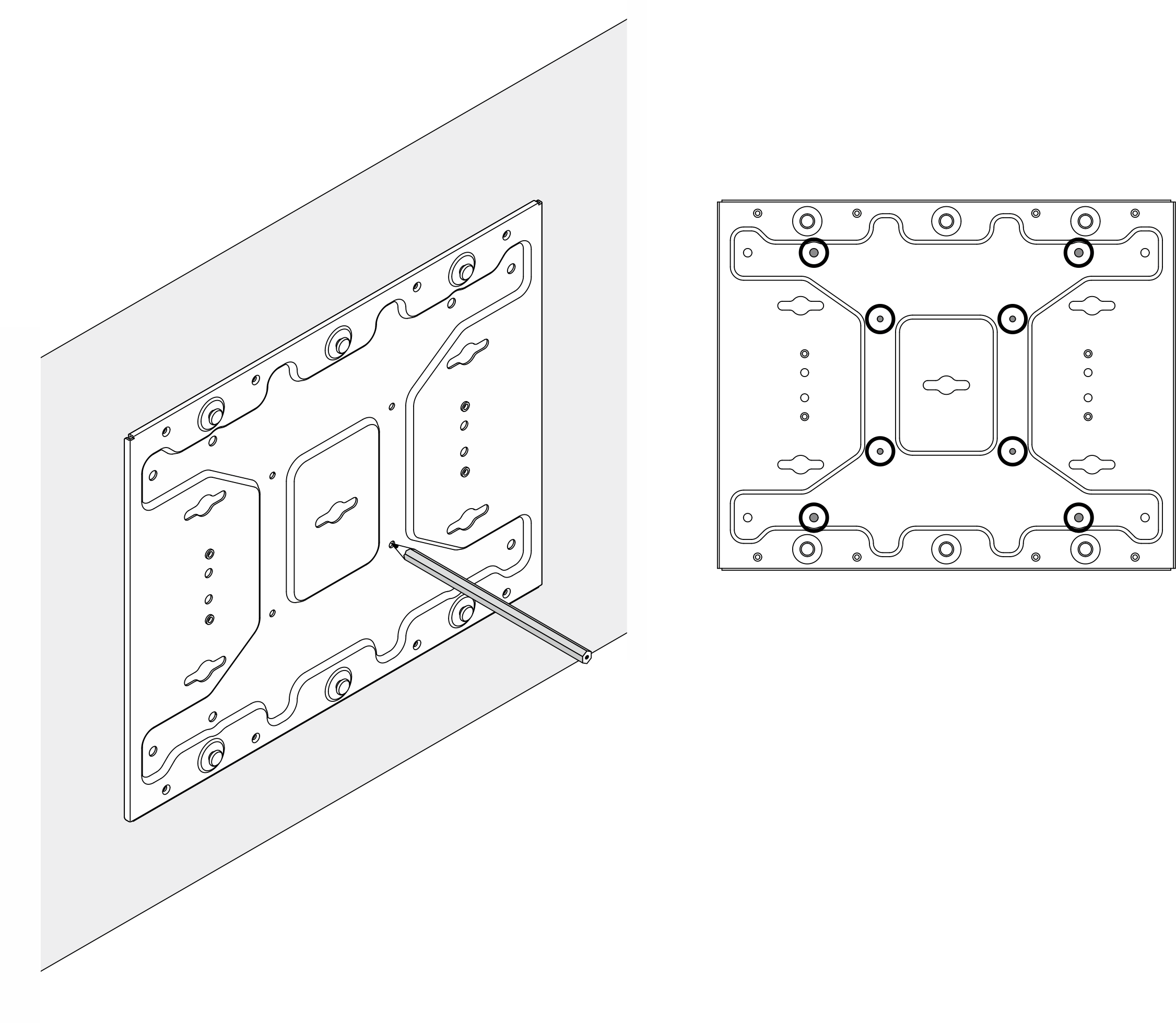
- Secure the wall-mount plate to the wall with four M4 screws and four M6 screws.Figure 8. Installing the wall-mount plate
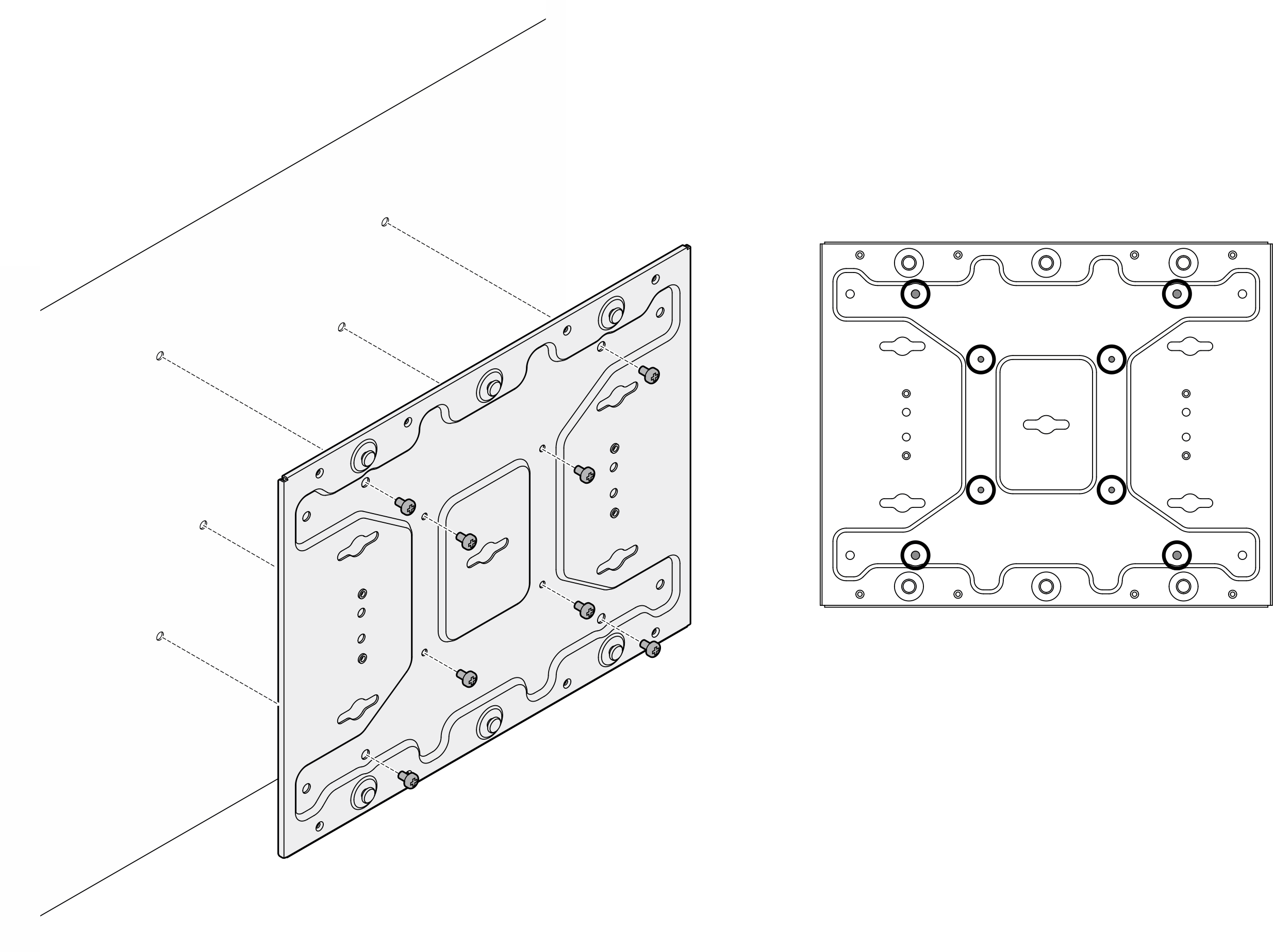 Figure 9. Locations of M4 screwsFigure 10. Locations of M6 screws
 - Install the node bracket to the wall-mount plate.
- Push the node bracket toward the wall-mount plate; then, slide the node bracket until the guide pins are seated in the small opening of keyholes.Figure 11. Installing the node bracket
- Secure the node sleeve with eight screws.Figure 12. Installing the node bracket
- Push the node bracket toward the wall-mount plate; then, slide the node bracket until the guide pins are seated in the small opening of keyholes.
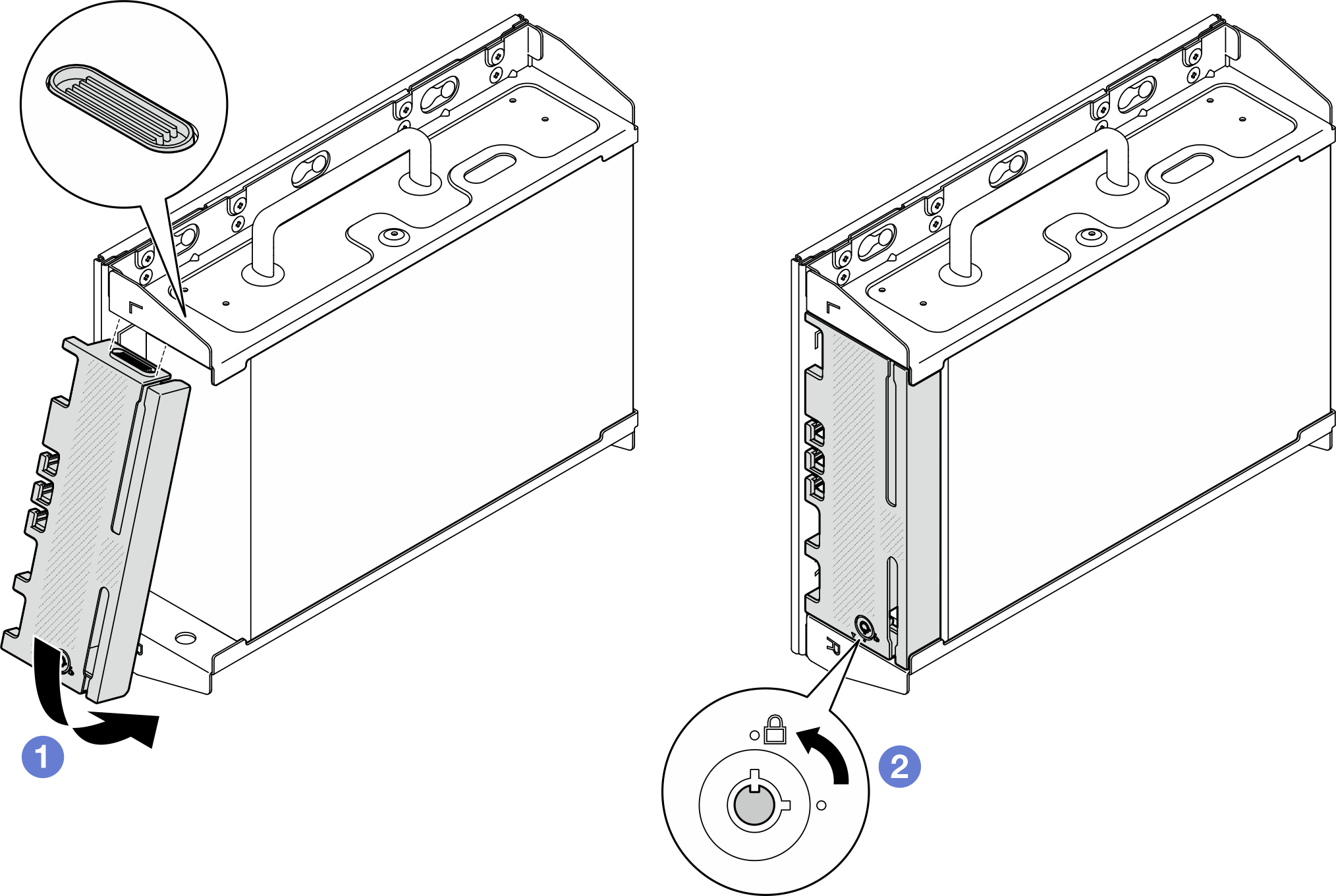
- (Optional) If necessary, install the security bezel.NoteWhen the security bezel is installed, the front operator panel and USB Type-C connectors are not accessible.
 Insert the tab of security bezel into the slot; then, pivot the security bezel toward the node sleeve until the other side of security bezel clicks into place.NoteMake sure that the external cables in front of the node go through the corresponding openings of the security bezel.
 Lock the security bezel with the key, and store the key for future use.
Figure 13. Installing the security bezel