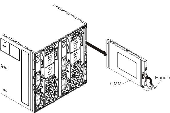
Removing a Chassis Management Module 2
Use these instructions to remove a Lenovo Chassis Management Module 2 modules from the Lenovo Flex System Enterprise Chassis.
Note
These instructions assume that the chassis is connected to power.
Before you remove a CMM, complete the following steps.
Important
If you have just installed a standby CMM in the chassis, do not remove the primary CMM until the Active LED on the standby CMM is lit (indicating that the standby CMM is controlling the chassis). The standby CMM requires about 2 minutes to become active and receive initial status information and firmware from the primary CMM.
- If the CMM that you are replacing is the only CMM in the chassis and the CMM is functioning, save the configuration file before you proceed.
- In the CMM web interface, configurations are saved in the Manage Configuration page (select Configuration from the Mgt Module Management menu). All fields and options are described in the CMM web interface online help.
- You can also use the write command in the CMM command-line interface (CLI). See write command for information about commands.
- If you are removing the primary CMM in the chassis, stop all CMM local and remote sessions before you proceed, to avoid an unexpected termination of sessions.
- Remove any external devices that block access to the rear of the chassis.
- Disconnect all cables from the CMM.
To remove the CMM, complete the following steps.

Give documentation feedback