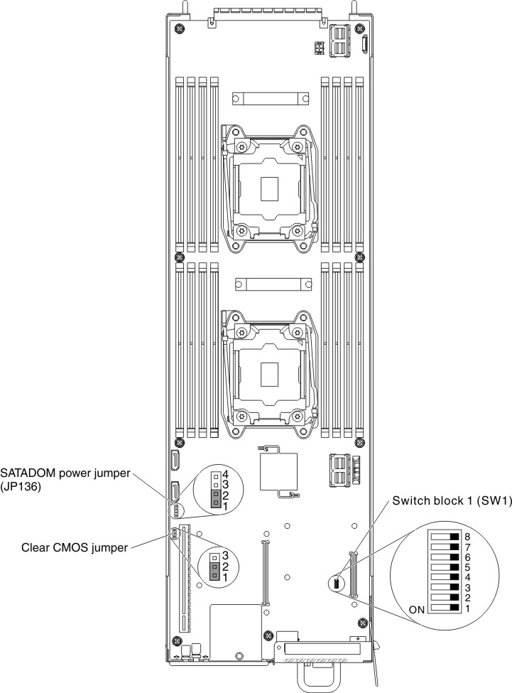
This section details the recovery BIOS Function by SW1.
- Pull out the node and place SW1 DIP1 to “ON” location.
Figure 1. Location of the switches, jumpers, and buttons on the system board
- Insert USB key (this USB key need include the Recovery ROM file “AMIBOOT.ROM”).
- Insert the node back into enclosure.
- Power on the server and wait system into recovery mode in setup menu.
- Select “Proceed with flash update” and Enter to start flash update.
- After update finish, please follow same procedure to remove USB key & place SW1 DIP1 to “OFF” location.