Chassis rear view
This section contains information on the rear of the chassis.
Note
Depending on the specific configuration, the hardware might look slightly different from the illustrations in this section.
Important
- For proper cooling, each node tray must be installed with either a node or node tray fillers before the nodes in the chassis are powered on.
Chassis rear view
Figure 1. Chassis rear view
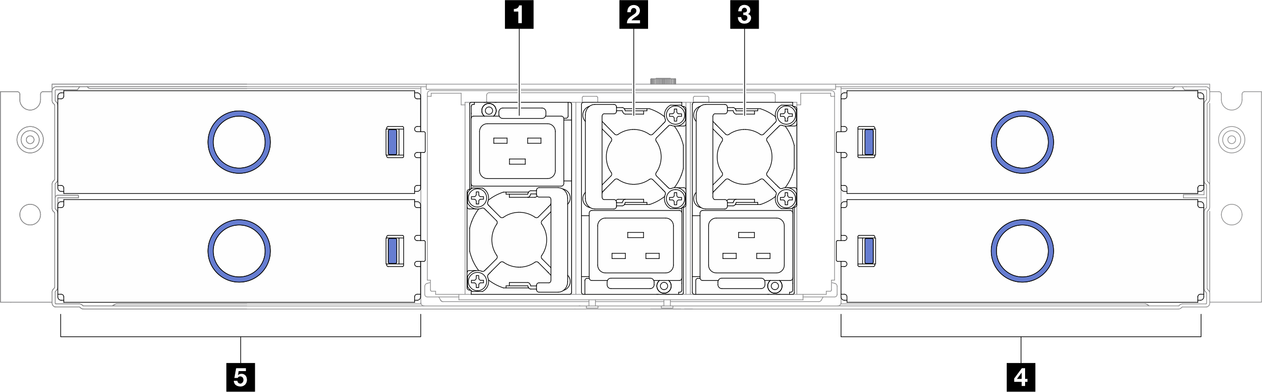
| 1 PSU slot 1 (the PSU must be installed with the fan downward) | 2 PSU slot 2 (the PSU must be installed with the fan upward) |
| 3 PSU slot 3 (the PSU must be installed with the fan upward) | 4 Node trays (the nodes must be installed right-side up) |
| 5 Node trays (the nodes must be installed upside down) |
1 / 2 / 3 PSU slots
Install power supply units to these slots, connect them to power cords. Make sure the power cords are connected properly.
Important
When installing the power supply units, make sure to follow the instruction on the label in each slot.
- For slot 1 (1), the PSU must be installed with the fan downward.
- For slots 2 and 3 (2 and 3), the PSU must be installed with the fan upward.
Following are the power supplies supported by the system:
- CRPS 1300-watt Titanium v1.1, input power 200-240V
- CRPS 2700-watt Platinum v1.3, input power 200-240V
- CRPS 2700-watt Platinum v1.4, input power 200-240V
- CRPS Premium (CFFv5) 2000-watt Titanium, input power 200-240V
- CRPS Premium (CFFv5) 2700-watt Titanium, input power 200-240V
For more information on the power supply LED, see Power supply LED.
Give documentation feedback