Install the DWC PSU manifold
Use this information to install the DWC PSU manifold.
About this task
The water might cause irritation to the skin and eyes. Avoid direct contact with the lubricant.


Read Installation Guidelines and Safety inspection checklist to ensure that you work safely.
Ensure proper handling procedures are followed when working with any chemically treated water used in the compute rack cooling system. Ensure that material safety data sheets (MSDS) and safety information are provided by the water chemical treatment supplier and that proper personal protective equipment (PPE) is available as recommended by the water chemical treatment supplier. Protective gloves and eyewear may be recommended as a precaution.
The task in this section requires two or more people.
Procedure
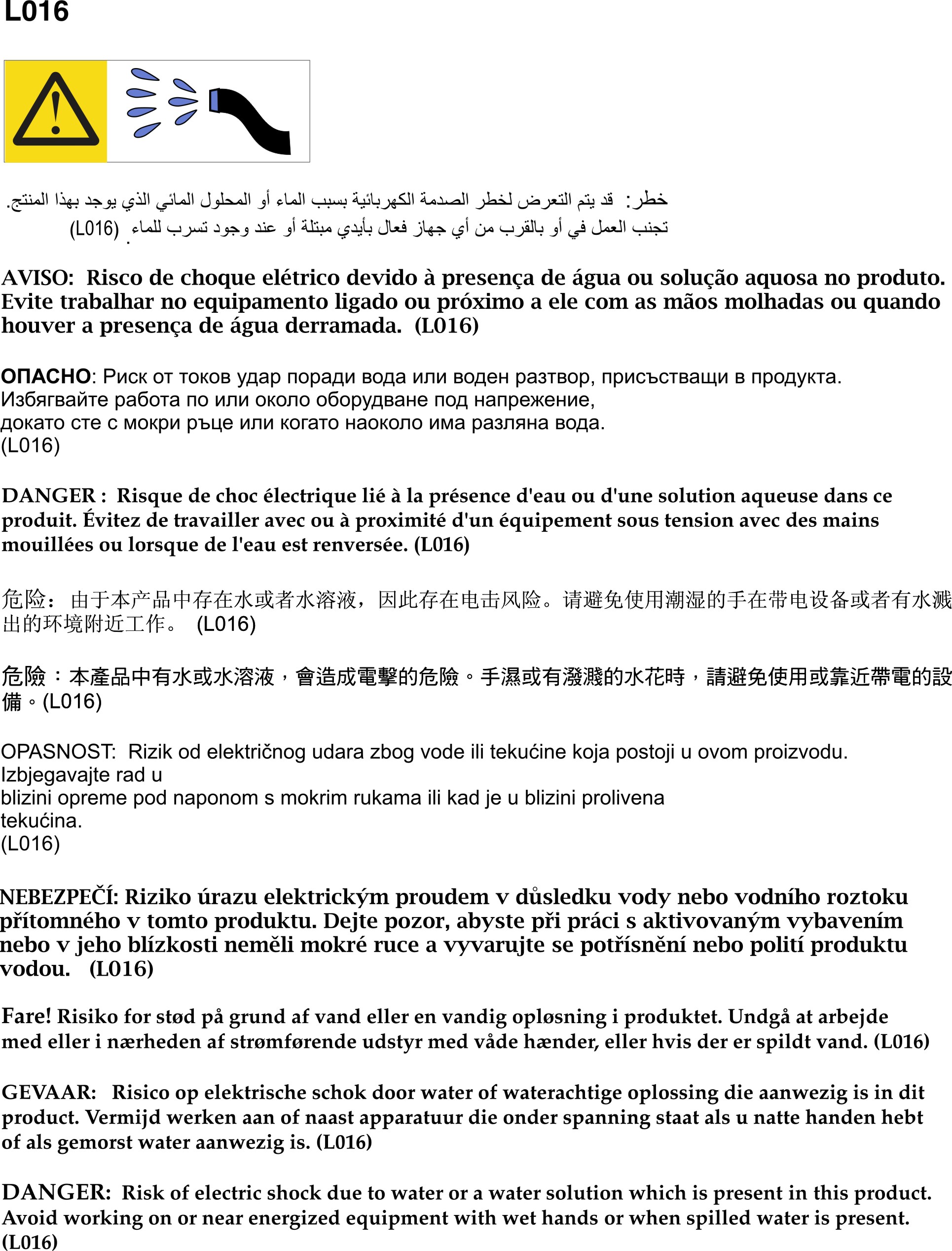
- Tighten four screws to secure the bottom rack manifold mounting bracket to the rack cabinet.Figure 1. Bottom rack manifold mounting bracket installation
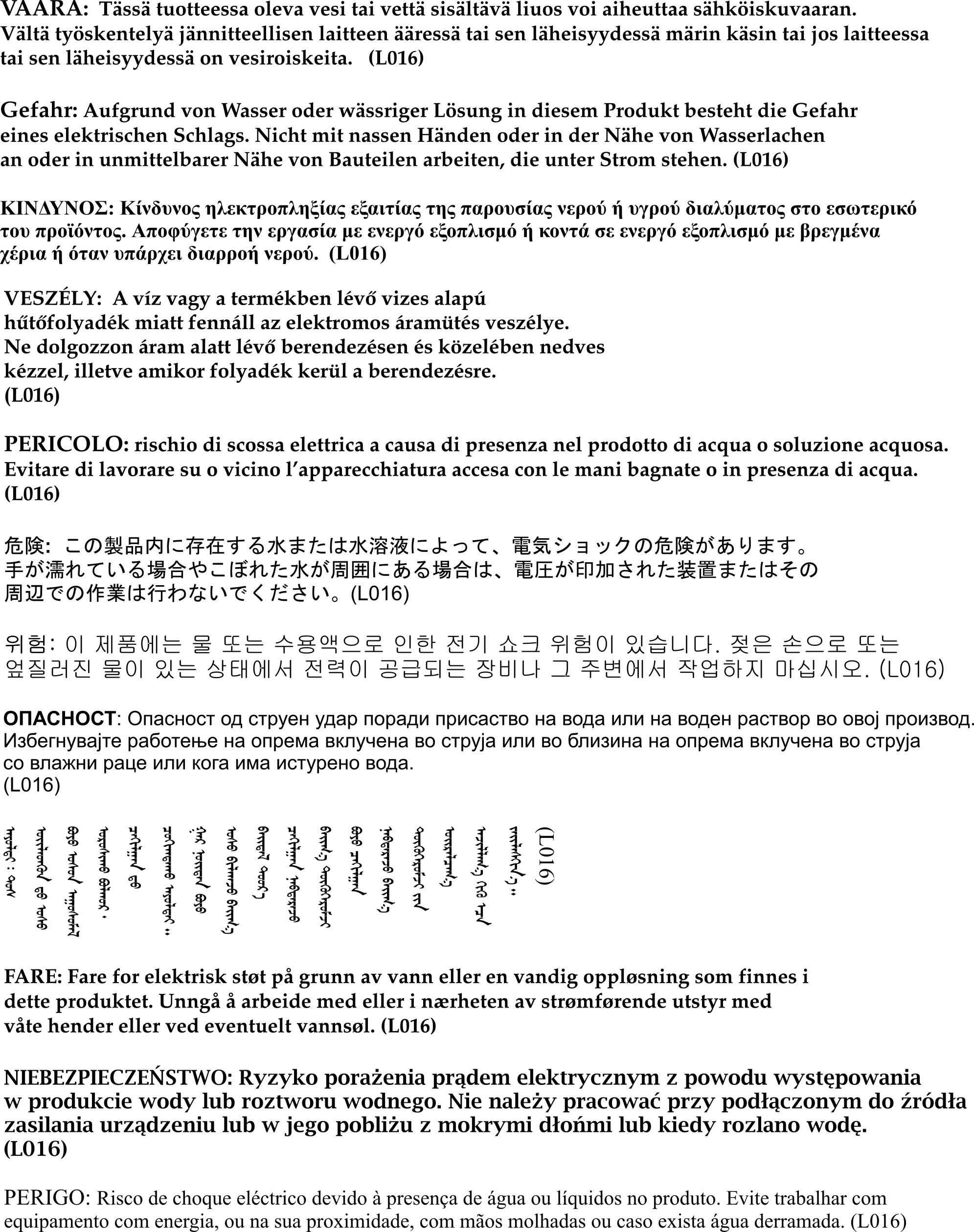
- Tighten six screws to secure the top rack manifold mounting bracket to the rack cabinet.Figure 2. Top rack manifold mounting bracket installation
- Install the DWC PSU manifold assembly.
 Route Supply/Return Hoses under bottom rack shipping bracket as shown.
 There are tabs on the bottom right and bottom left of the manifold. On each tab there is a retention slot. Position the tabs at an angle while aligning the retention slots to the threaded studs; then, insert the tabs into the tab slots on the bottom rack manifold mounting bracket.
1 Bottom rack shipping bracket 2 Bottom rack manifold mounting bracket 3 Tab slot on 2 4 Tab on the bottom of the manifold 5 Retention slot on the bottom of the manifold 6 Threaded stud on 2 Figure 3. DWC PSU manifold assembly installation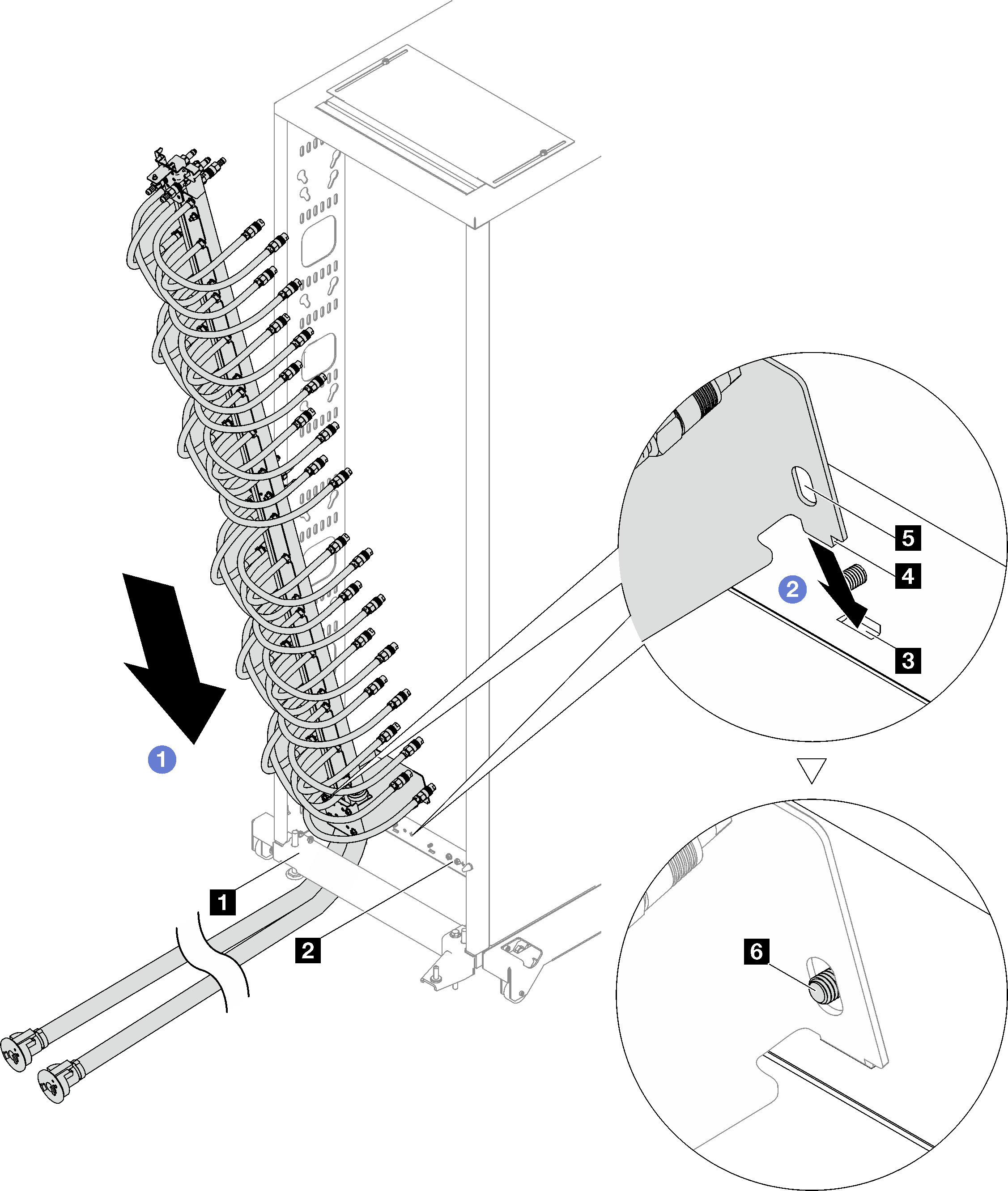
 Rotate the top part of the DWC PSU manifold assembly into the rack cabinet as shown.
 Make sure the threaded studs stick through the retention slot.
 Make sure the plunger is secured in place.
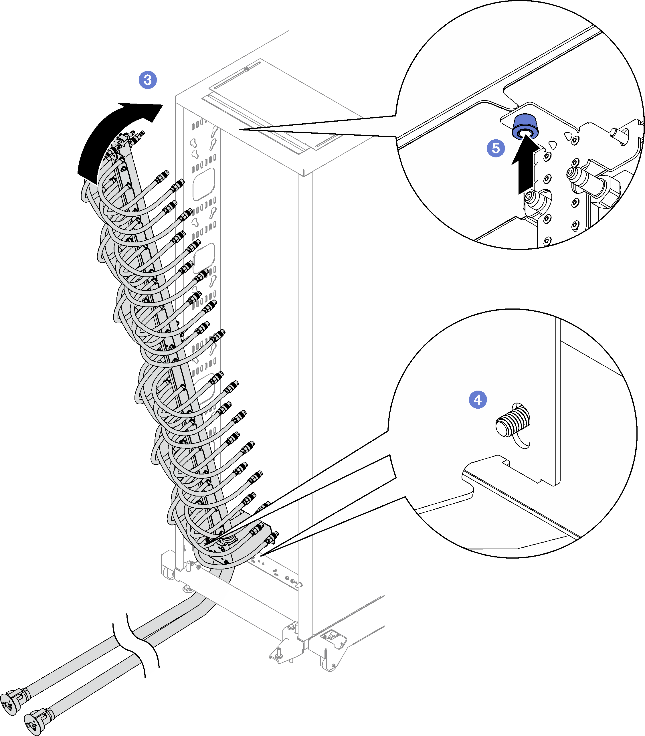
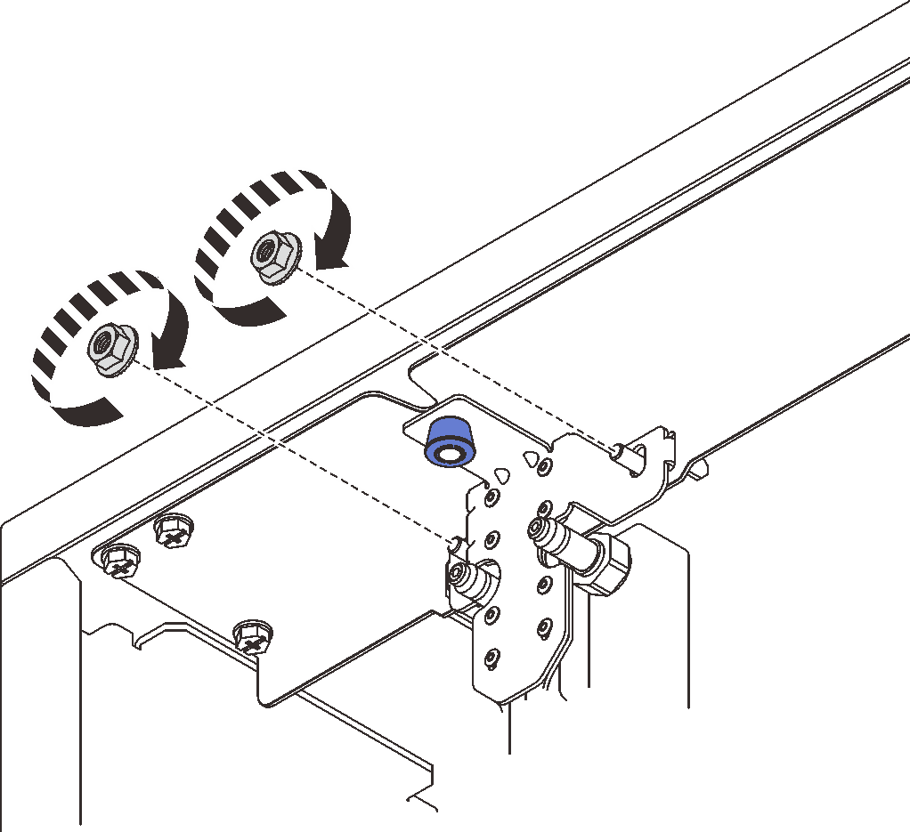
- Install and tighten the two nuts on the top rack manifold mounting bracket as shown.Figure 4. Top rack manifold mounting bracket nuts installation
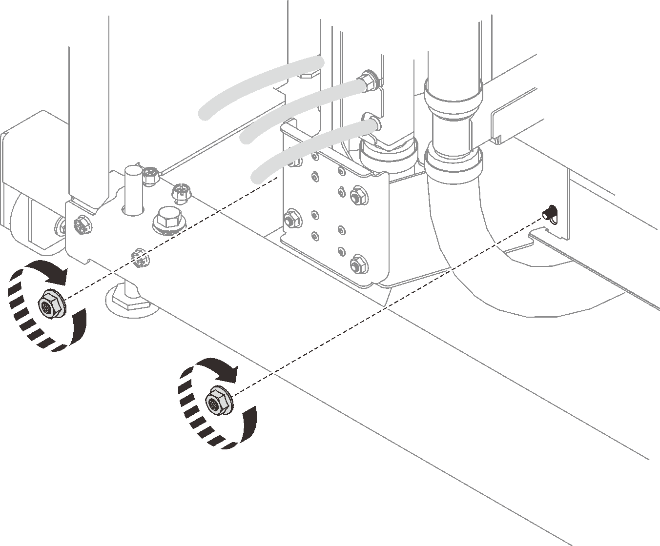
- Install and tighten the two nuts on the bottom rack manifold mounting bracket as shown.Figure 5. Bottom rack manifold mounting bracket nuts installation
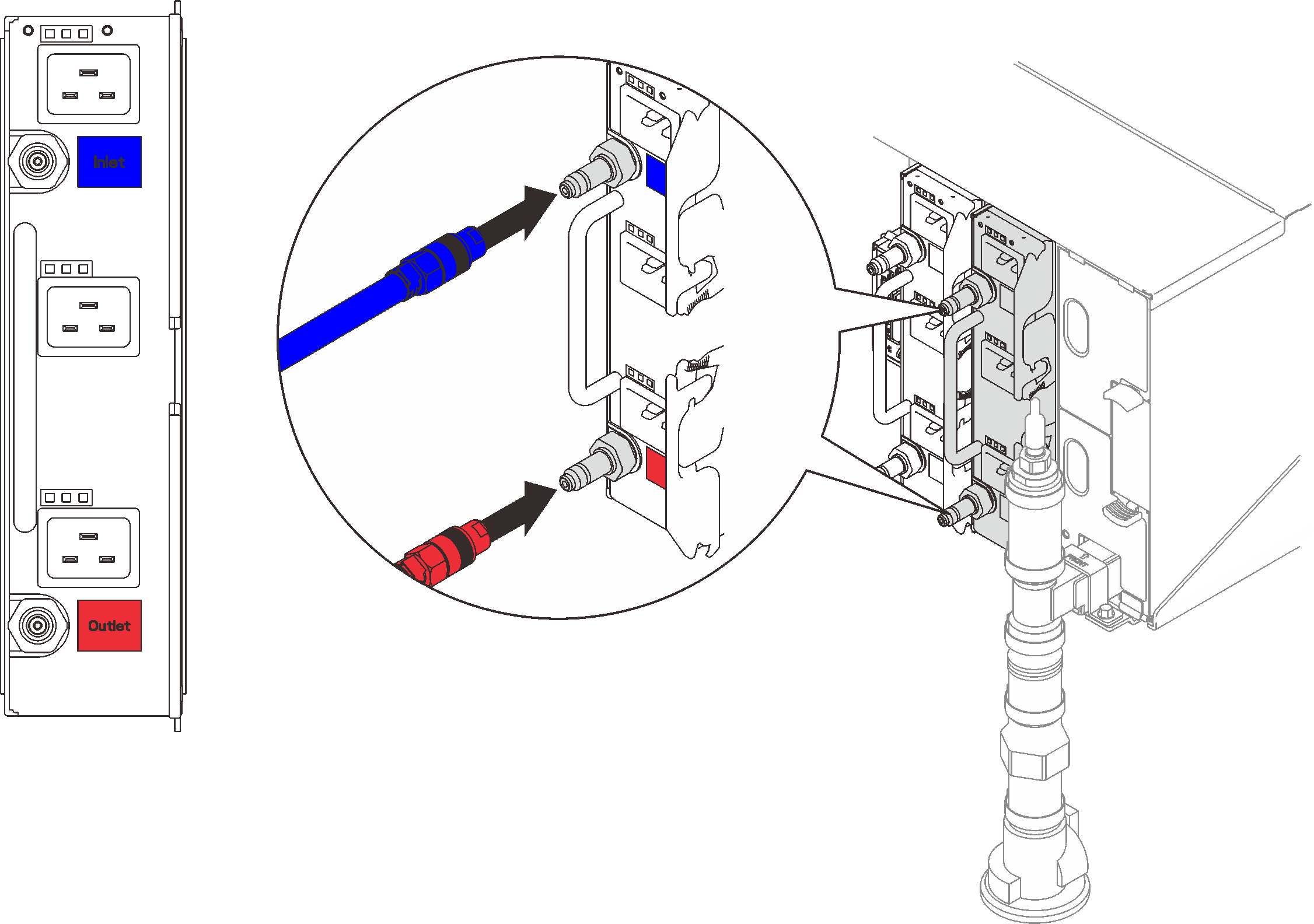
- Connect the DWC PSU manifold hose assembly to the DWC power supply quick connect.Figure 6. DWC PSU hose assembly installation
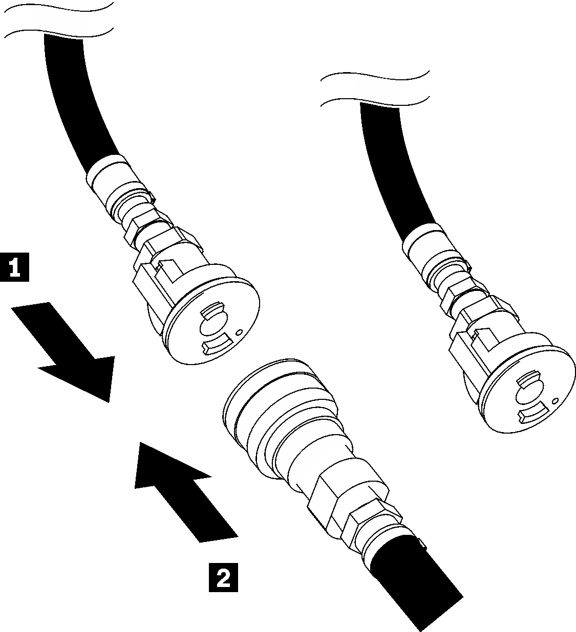
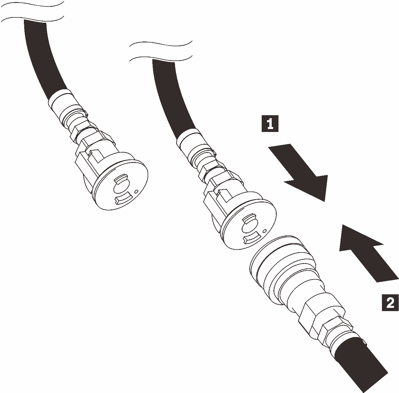
- At the front of the rack, connect the facility supply hose to the rack return hose. Press the unlock pin and partially open the supply hose, about 1/4 of the way.NoteDo not fully open the facility ball valve or you will reduce your ability to control the flow as you fill the rack.Figure 7. Facility supply hose to rack return hose connection
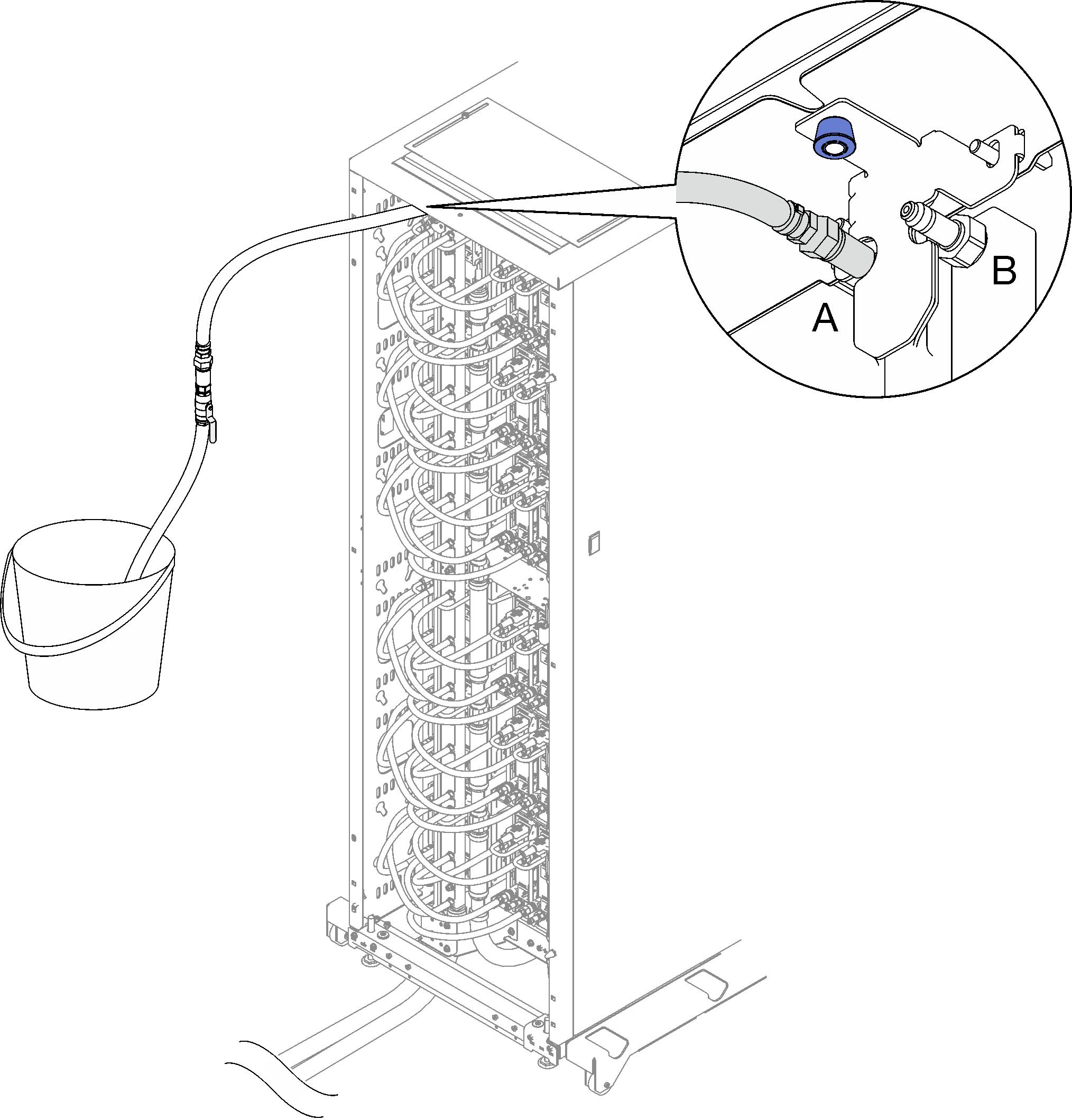
1 Rack return (DWC PSU manifold) 2 Facility supply (DWC PSU manifold) - Connect the hose assembly (supplied to customer installation site) to the top quick connect at Location A (top of the DWC manifold) and place the other end in a bucket. Slowly open the hose valve to allow air to flow out of the hose. Close the hose valve once a steady stream of water flows into the bucket or there are minimal bubbles in the sight-glass.Figure 8. Hose assembly at Location A
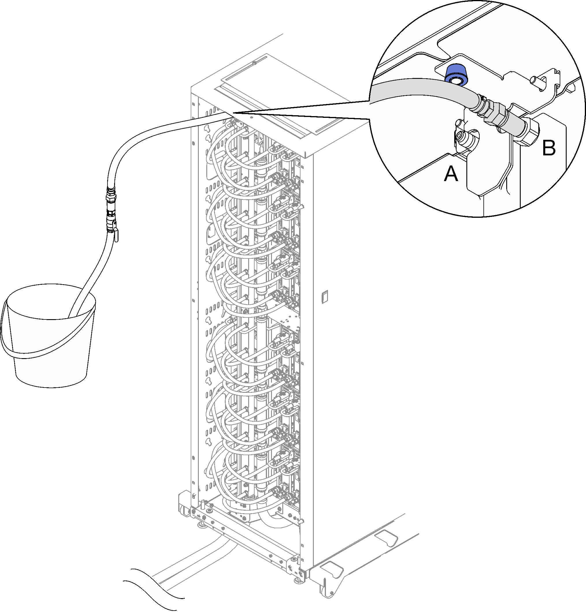
- Disconnect the hose assembly from Location A and connect it to Location B. Slowly open the hose valve to allow air to flow out of the hose. Close the hose valve once a steady stream of water flows into the bucket or there are minimal bubbles in the sight-glass.Figure 9. Hose assembly at Location B
- Go to the front of the rack, disconnect the facility supply hose from the rack return hose and connect the facility supply hose to the rack supply hose.Figure 10. Facility supply hose to the rack supply hose connection
1 Rack supply (DWC PSU manifold) 2 Facility supply (DWC PSU manifold) - Once completed, go back to the front and connect the facility return hose to the rack return hose. Fully open all connections on both the supply and return side. The DWC PSU manifold should be completely filled.Figure 11. Facility return hose to the rack return hose connection
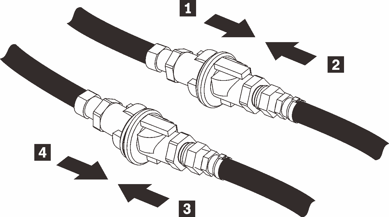
1 Rack supply (DWC PSU manifold) 3 Facility return (DWC PSU manifold) 2 Facility supply (DWC PSU manifold) 4 Rack return (DWC PSU manifold)
Demo video