System Management Module 2 (SMM 2)
The following illustration shows the connectors and buttons on the SMM2 module.
For SMM2 LEDs, see System Management Module 2 (SMM 2) LEDS.
Figure 1. SMM2 connectors
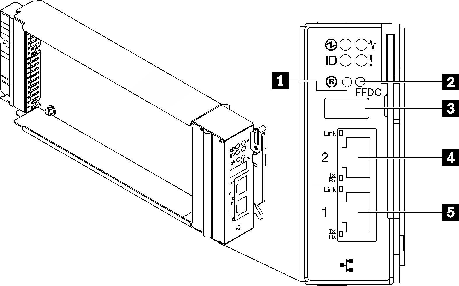
| 1 Reset button hole | 4 Ethernet port 2 |
| 2 USB port service mode button (FFDC dump) | 5 Ethernet port 1 |
| 3 USB 2.0 connector |
1 Reset button: Press the button for 1 to 4 seconds, SMM2 reboots. Press over 4 seconds, SMM2 reboots and loads to the default settings.
2 USB port service mode button (FFDC dump): Press this button to collect FFDC logs after inserting the USB storage device to the USB 2.0 connector.
3 USB 2.0 connector: Insert the USB storage device to this connector and then press the USB port service mode button to collect FFDC logs.
4 Ethernet port 2: Use this connector to access SMM2 management.
5 Ethernet port 1: Use this connector to access SMM2 management.
Give documentation feedback