Power supplies
The Flex System Enterprise Chassis supports up to six autoranging power supplies.
The types of power supplies that are available for the Flex System Enterprise Chassis are listed in Table 1.
| Rated output | Input voltage range | Power cord connector | FRU numbers |
|---|---|---|---|
| 2100 W | 200 to 240 V ac | C20 | 94Y8253 or 69Y5892 |
| 2500 W | 200 to 240 V ac | C20 | 94Y8251 or 69Y5890 |
| 2500 W | 240 to 380 V dc1 | RF-203 | 94Y8274 |
| 2500 W | -48 to -60 V dc | 2 position power connector | 94Y8265 |
| 1. Tolerance 192 - 400 V dc. | |||
The power supplies get electrical power from either a 200 to 240 V ac power source, a 240 to 380 V dc power source, or a -48 to -60 V dc power source depending on the type of power supply. Both ac and dc-powered supplies convert the power source into 12 V dc and 3.3 V dc outputs to the system midplane. The power supplies are capable of autoranging within the input voltage range. There is one common power domain for the chassis that distributes dc power to each of the nodes and modules through the system midplane.
Power supply redundancy is achieved when there is one more power supply available than is needed to provide full power to all chassis components. Power source redundancy is achieved by distributing the power cord connections between independent supply circuits. See Connecting the chassis to power for more information.
Each power supply has internal fans and a controller. The power supply controller can be powered by any installed power supply that is providing dc power through the midplane. The power supply does not have to be connected to a power source to communicate with the CMM, as long as dc power is available from the midplane.
Up to six power supplies can be installed. The number of power supplies that you install is dependent on the type of power supply, the chassis power load, and selected chassis power policy.
- Mixing ac-powered supplies with dc-powered supplies in the same chassis is not supported. Each chassis must contain either all ac-powered supplies or all dc-powered supplies.
- For ac-powered chassis, do not mix 2100 W and 2500 W power supplies. Chassis powered by ac power should contain only power supplies of the same wattage.
- For dc-powered chassis, do not mix 240 to 380 V dc and -48 to -60 V dc power supplies. Chassis powered by dc power should contain only power supplies of the same input voltage.
For example, if a 2100 W power supply is installed in a chassis containing 2500 W power supplies, the CMM will budget power as if all of the power supplies are 2100 W. In this scenario, the Fault LED on the mismatched power supply and the chassis Fault LED are lit and a warning message is sent to the CMM event log. In addition, if the chassis power budget is insufficient, the CMM might not allow all of the devices in the chassis to power on.
- 200 - 208 VAC, 3-Phase Delta power distribution units (PDUs): The power supplies are designed so that three power supplies will consume the power of and balance the phases of a 30 A, 3-phase PDU; or six power supplies will consume the power of and balance the phases of a 60 A, 3-phase PDU.
- 380 - 450 VAC, 3-Phase Y PDU: The power supplies are designed so that three power supplies will nearly consume the power of and balance the phases of a 16A, 3-phase PDU, or six power supplies will nearly consume the power of and balance the phases of a 32 A, 3-phase PDU.
- Single-phase PDUs can be used, however, the building power service may be unbalanced and the PDU power may not be fully utilized.
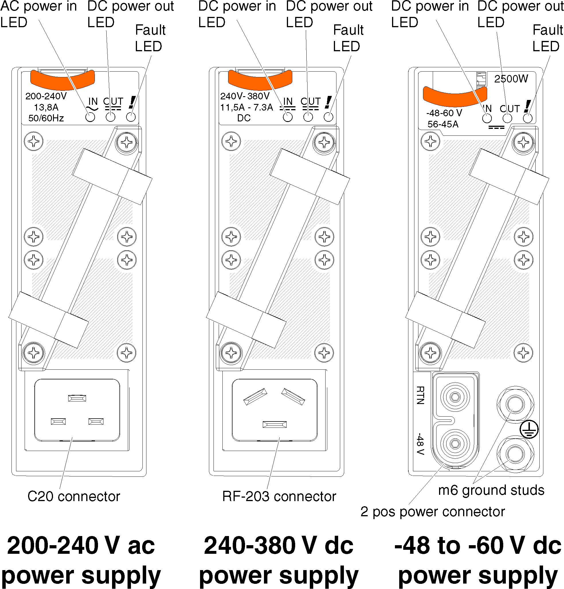
Power supply controls and indicators
- AC power in LED (200 - 240 V ac supplies only)

When this LED is lit (green), it indicates that ac power is being supplied to the power supply.- DC power in LED (240 to 380 and -48 to -60 V dc supplies)

When this LED is lit (green), it indicates that dc power is being supplied to the power supply.- DC power out LED

When this LED is lit (green), it indicates that dc power is being supplied from the power supply to the chassis midplane.- Fault LED

When this LED is lit (yellow), it indicates that there is a fault with the power supply.NoteBefore unplugging the ac power cord from the power supply or removing the power supply from the chassis, verify that the capacity of the remaining power supplies are sufficient to meet the minimum power requirements for all components in the chassis. You can view the power status and requirements through theFlex System Manager. For information on accessing and using the Flex System Manager, see the Flex System Manager information page.