
Routing cables/hoses for water-cooled system

Adopt one of the following procedures, depending on whether the rack is in a raised-floor environment.

Important
To help maintain optimal performance and provide proper cooling for all rack components, always take the following precautions:
  • Install filler panels over all unoccupied bays.
  • Route signal cables at the rear of the rack so that they enter or exit the cabinet through the top and bottom air baffles.
    Figure 1. Managing cables with the upper air baffle

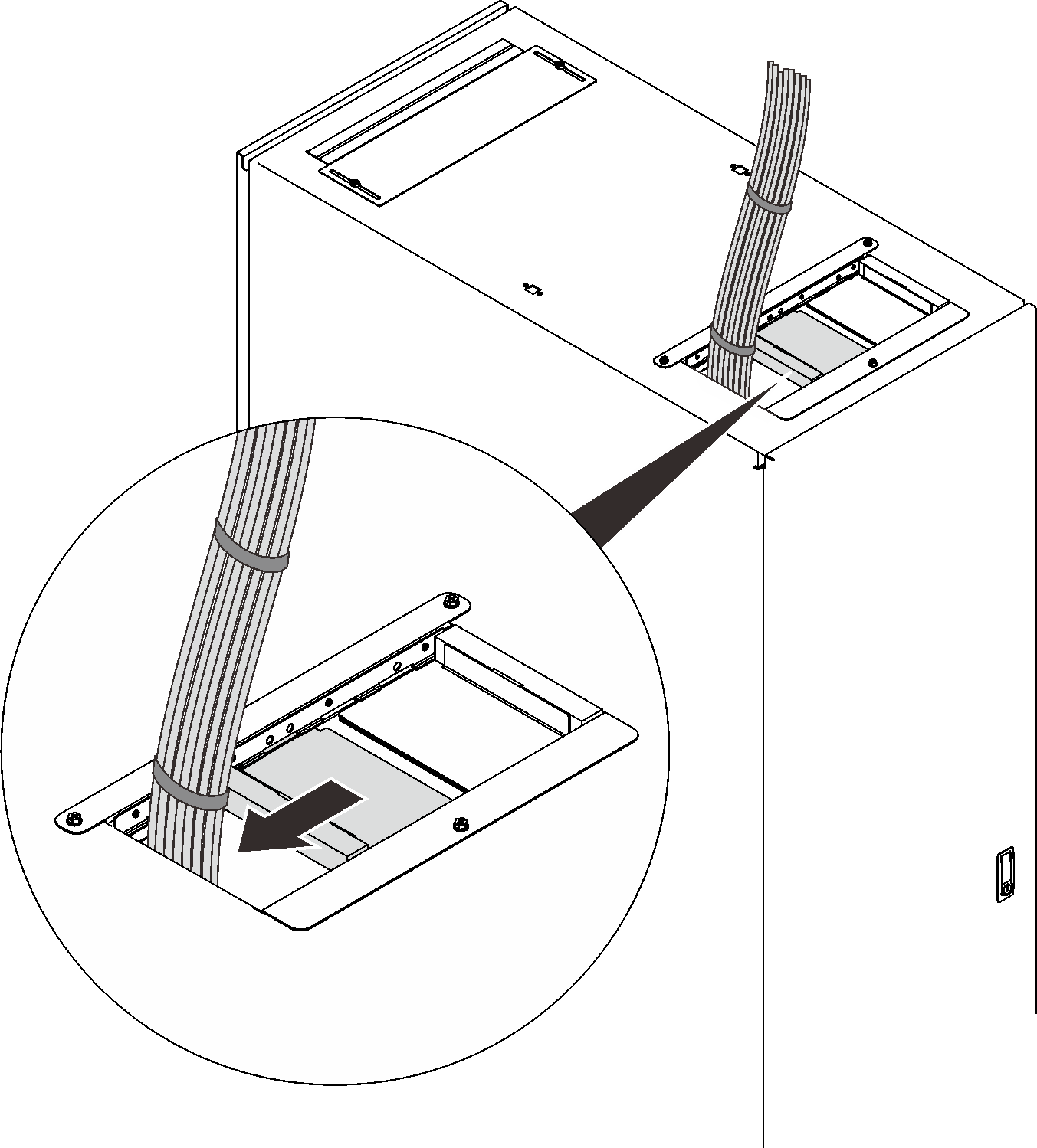
    Figure 2. Managing cables with the lower air baffle

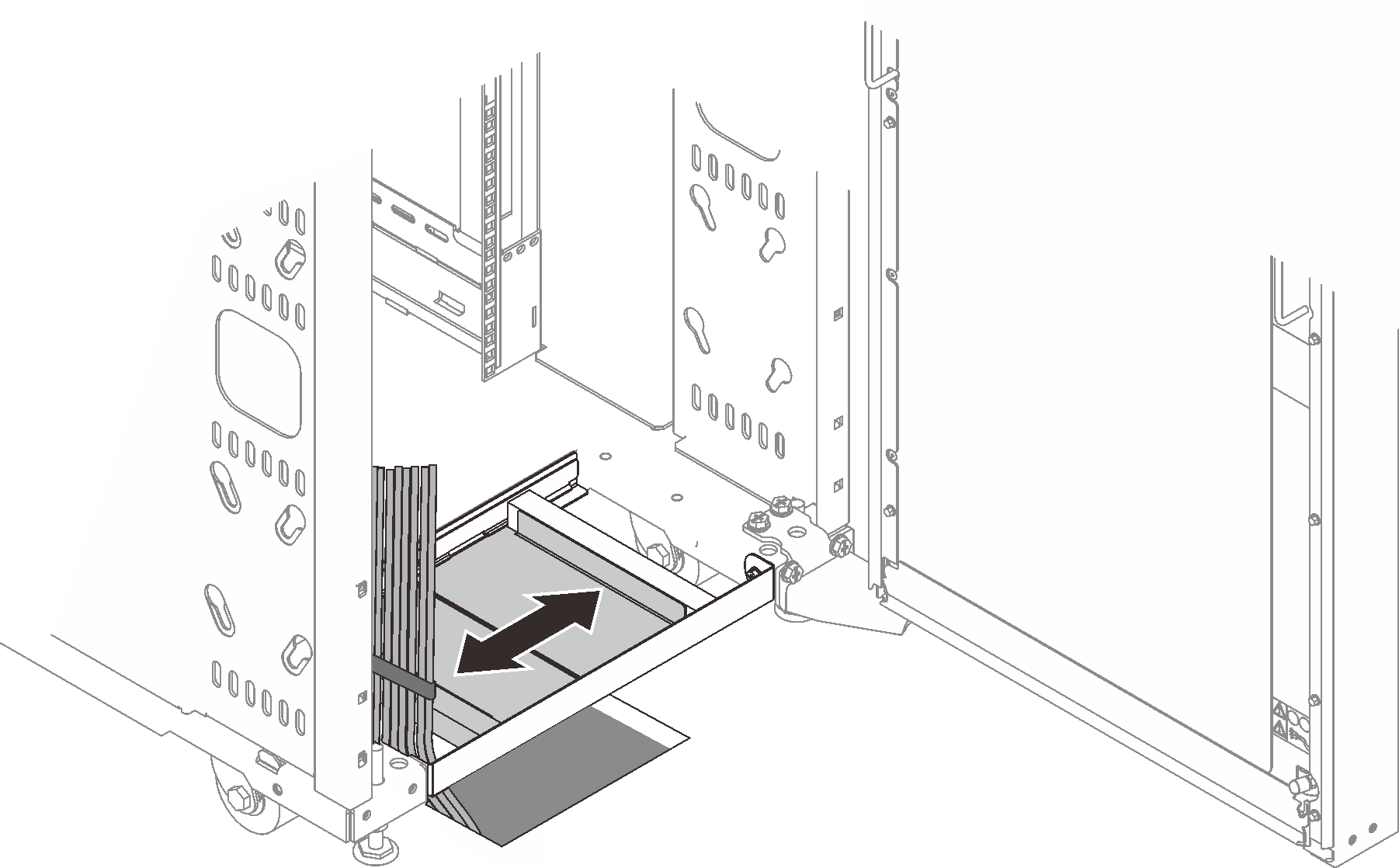
  • Bundle signal cables together in a rectangle so that the air-baffle sliders are closed as far as possible. Do not bundle signal cables together in a circular formation.

Raised-floor environment

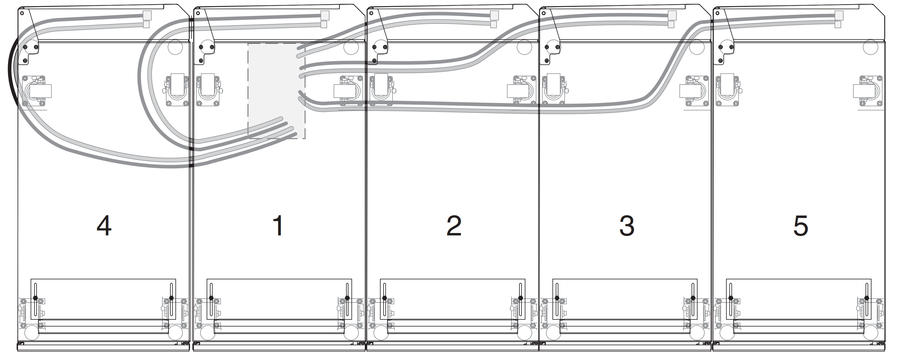
The following illustrations show routing and securing the hoses in a raised-floor environment for individual racks and adjacent racks.

Figure 3. Routing and securing the hoses in a raised-floor environment for individual racks (from the top, looking down)

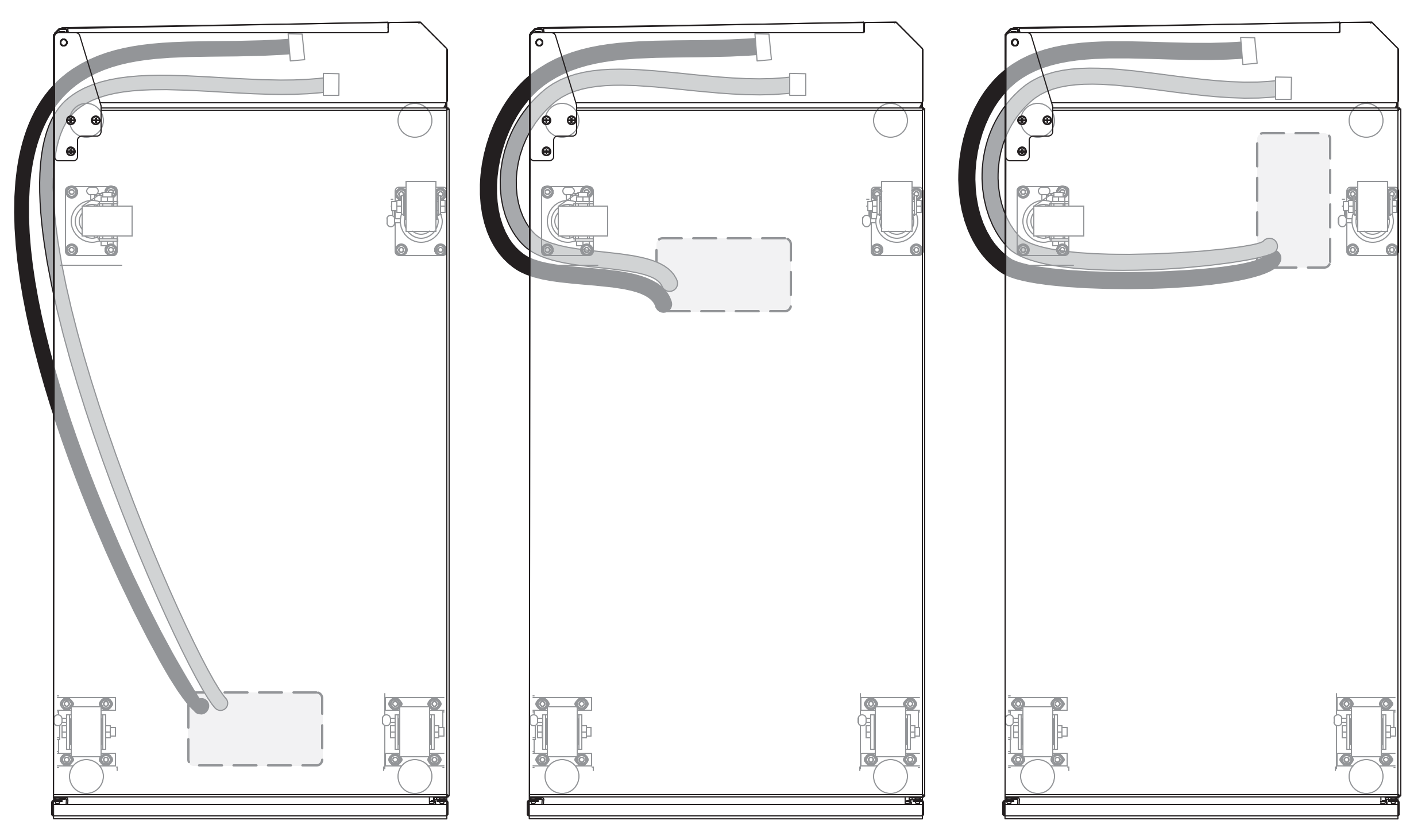
In the following illustration, the numbers represent the suggested placement of racks that share one hole in the floor. For example, if three racks will share one hole in the floor, place the racks as shown by the numbers 1, 2, and 3. If you want to add a fourth rack that will share the same hole in the floor, place it next to rack number 1.

Figure 4. Option for hoses in adjacent racks to share a single hole in the floor (from the top, looking down)

To route and secure the hoses in a raised-floor environment, complete the following steps:

  1. Remove the floor tile under the rack that will have an access hole cut into it.
  2. Cut an access hole in the floor tile; then, reinstall the floor tile. The access hole for the supply and return hoses must be a minimum of 200 mm (8 in.) long x 100 mm (4 in.) wide.
    Note
    • Each hose must be routed through the access hole lengthwise so that the hose has the entire 200 mm (8 in.) to pass through the floor. If adjacent racks share a hole in the floor, increase the size of the hole according to the number of hoses, 50 mm (2 in.) in length for every rack. For example, the hole for one rack is 100 x 200 mm (4 x 8 in.), the hole for two racks is 150 x 200 mm (6 x 8 in.), and so on. Smaller hole sizes might also work, depending on the hose routing underneath the raised floor.
    • Each hose must be routed with a minimum bend radius of 200 mm (8 in.). A bend radius less than 200 mm (8 in.) will cause the hose to kink, will restrict the flow of water to and from the heat exchanger, and will void the heat exchanger warranty.
  3. Route the hoses through the access hole lengthwise, under the rack and around the rear caster on the pivot side of the heat exchanger. See “Filling the heat exchanger with water” on page 48 for information about how to connect the hoses.
  4. Check the heat exchanger for air in the manifolds again after one month of operation, to ensure that the heat exchanger is filled correctly.

Raised-floor and non-raised-floor environments

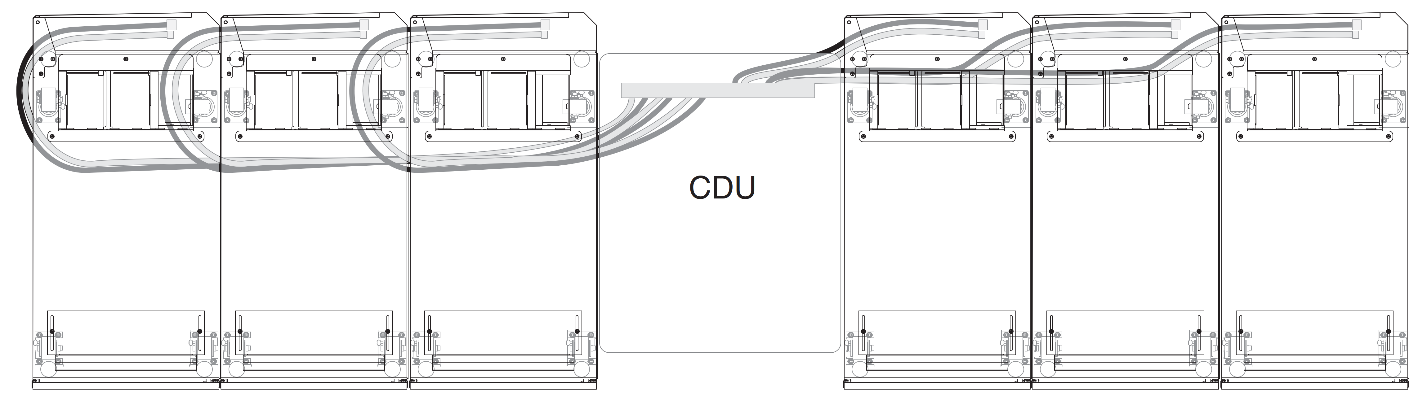
If the coolant distribution unit (CDU) that is providing water to the heat exchanger is in a row of racks with heat exchangers, all hoses can be routed on the floor, irrespective of if it is a raised floor or slab installation. The Type 9363 rack has sufficient clearance underneath the rack to enable the quick connects to be run underneath the rack. This provides a very clean hose-routing solution with hoses of minimum length.

Note
Each hose must be routed with a minimum bend radius of 200 mm (8 in.). A bend radius less than 200 mm (8 in.) will cause the hose to kink, will restrict the flow of water to and from the heat exchanger, and will void the heat exchanger warranty.
  1. If the hoses must be run overhead, either route the hoses through the rack vertically, or route them vertically down the hinge (pivot) side of the heat exchanger, leaving enough slack in the hoses to reach the couplings.
    Figure 5. Routing and securing the hoses in raised-floor and non-raised-floor environments (from the top, looking down)

  2. After several hours of operation, repeat the air-purging procedure on the valve (trapped air from the hoses might have migrated to the heat exchanger). To perform the air-purging procedure, complete step 7 on page 52 through step 10 on page 52 in Filling the heat exchanger with water.
  3. Check the heat exchanger for air in the manifolds again after one month of operation, to ensure that the heat exchanger is filled correctly.