Internal cable routing
See this section to do cable routing for specific components.
Turn off the server before you connect or disconnect any internal cables.
See the documentation that comes with any external devices for additional cabling instructions. It might be easier for you to route cables before you connect the devices to the server.
Cable identifiers of some cables are printed on the cables that come with the server and optional devices. Use these identifiers to connect the cables to the correct connectors.
Ensure that the cable is not pinched and does not cover any connectors or obstruct any components on the system board.
Ensure that the relevant cables pass through the cable clips.
Connect cable connectors vertically or horizontally in alignment with the orientations of the corresponding cable sockets, avoiding any tilt.
- To disconnect cables from the system board, do as follows:
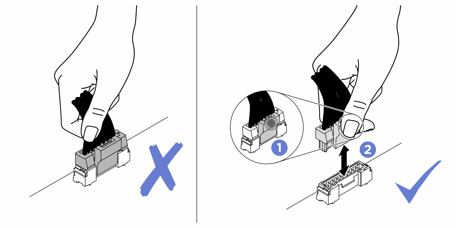
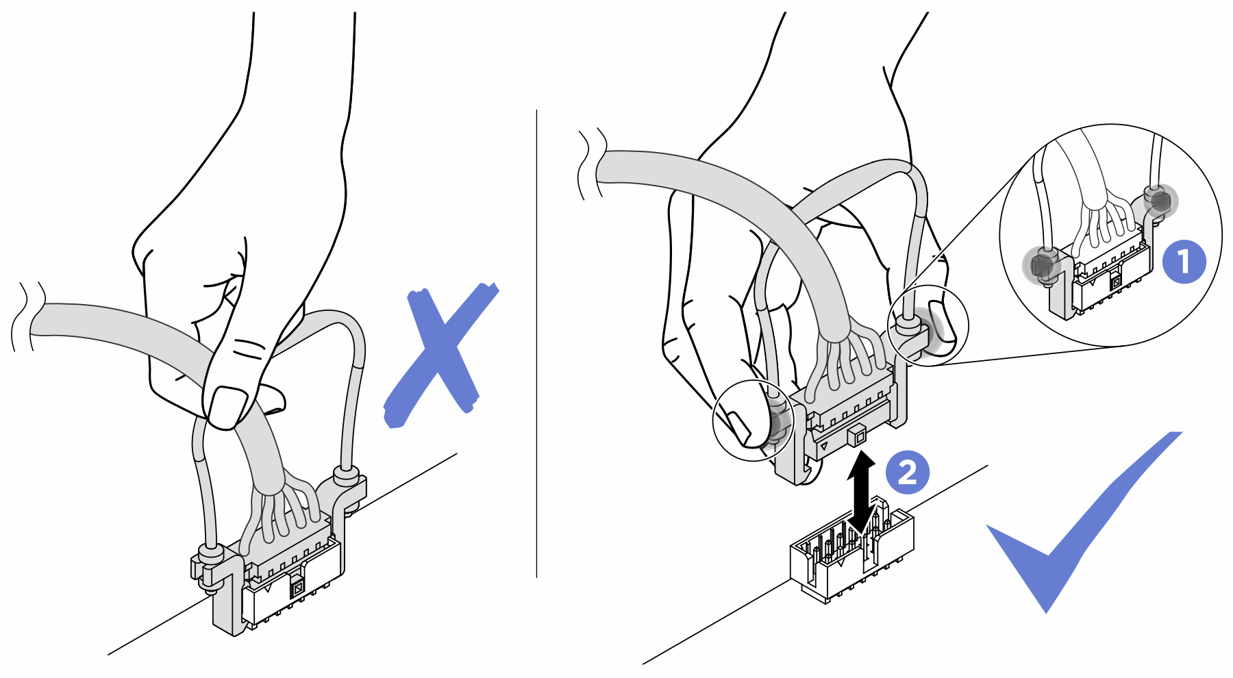
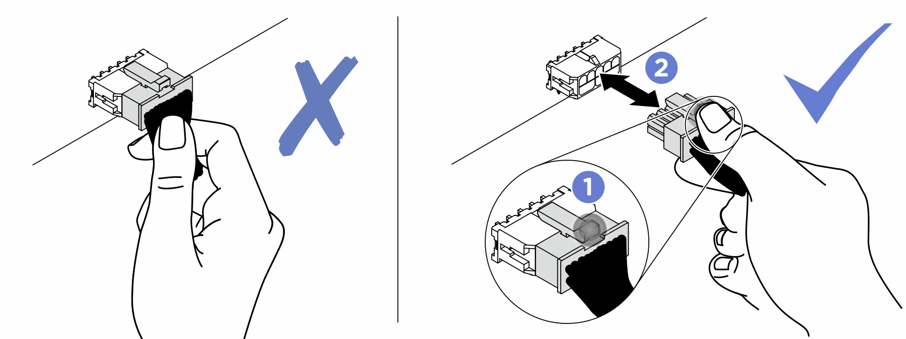
Press and hold all latches, release tabs, or locks on cable connectors to release the cable connectors.
- Remove the cable connectors vertically or horizontally in alignment with the orientations of the corresponding cable sockets, avoiding any tilt.NoteThe cable connectors might look different from those in the illustration, but the removal procedure is the same.
| Routing priority | Cable routing section |
|---|---|
| 1. Rear backplane signal cable | Cable 2 in Cable routing for rear drive backplane |
| 2. Rear backplane power cable | Cable 1 in Cable routing for rear drive backplane |
| 3. PIB signal cable | Cable 3 in Cable routing for power input board (PIB) |
| 4. PIB power cable 0 | Cable 1 in Cable routing for power input board (PIB) |
| 5. PIB power cable 1 | Cable 2 in Cable routing for power input board (PIB) |
| 6. Front backplane power cable 1 | Cable 1 in Cable routing for front backplane power |
| 7. Front backplane power cable 2 | Cable 2 in Cable routing for front backplane power |
| 8. Front backplane power cable 3 | Cable 3 in Cable routing for front backplane power |
| 9. Front backplane signal cables 1–3Note | Cable 1 2 3 in Cable routing for front backplane signals |