Installing the rail kit
Follow the instructions in this section to install or remove the rail kit.
This cabinet supports the following servers and corresponding rail kits. Follow the instructions to install them into the cabinet.
Install the rail kit and SE350 E1 Enclosure (1U2N)
About this task
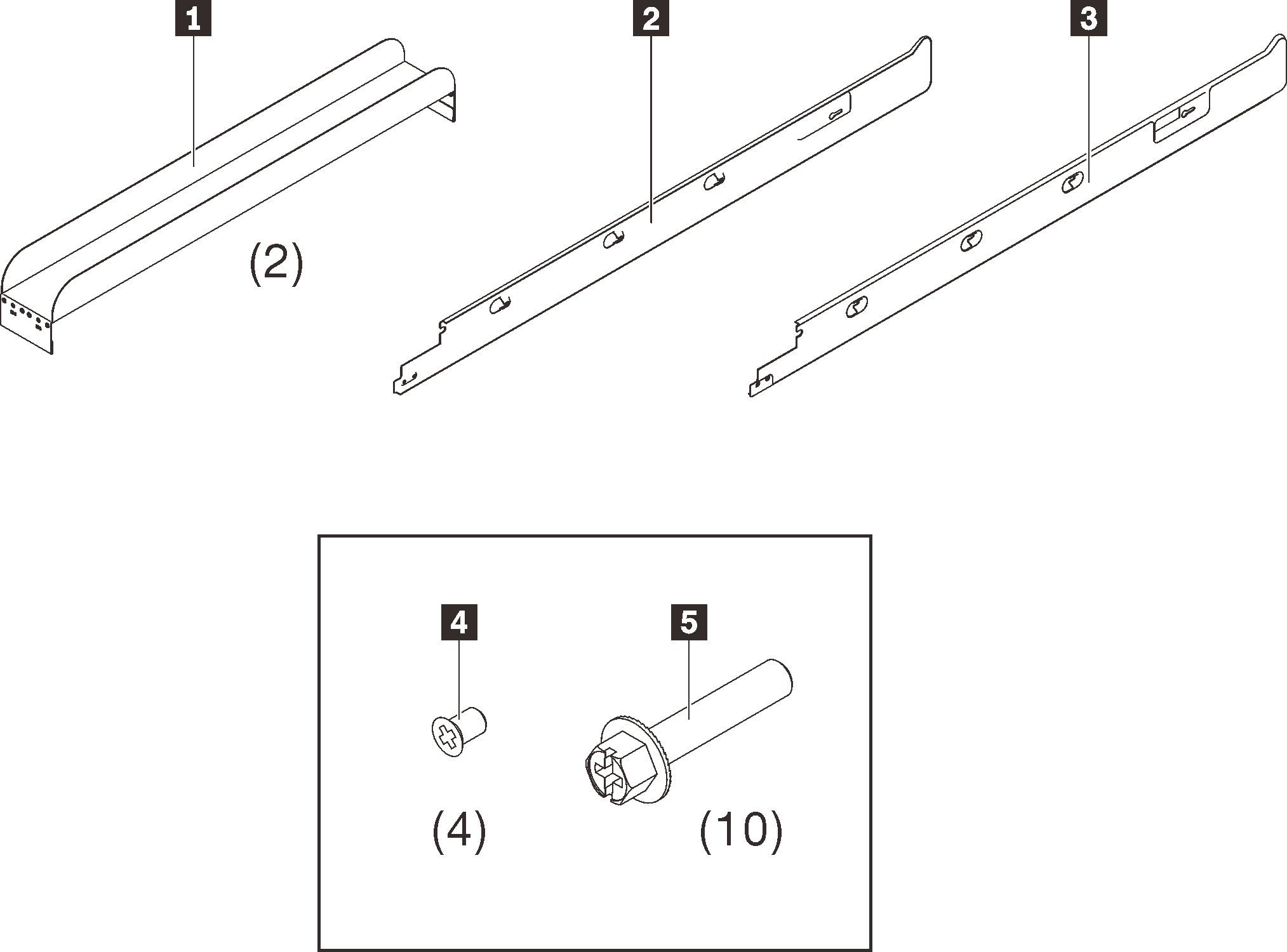
See the following table to identify the components that come with the rail kit.
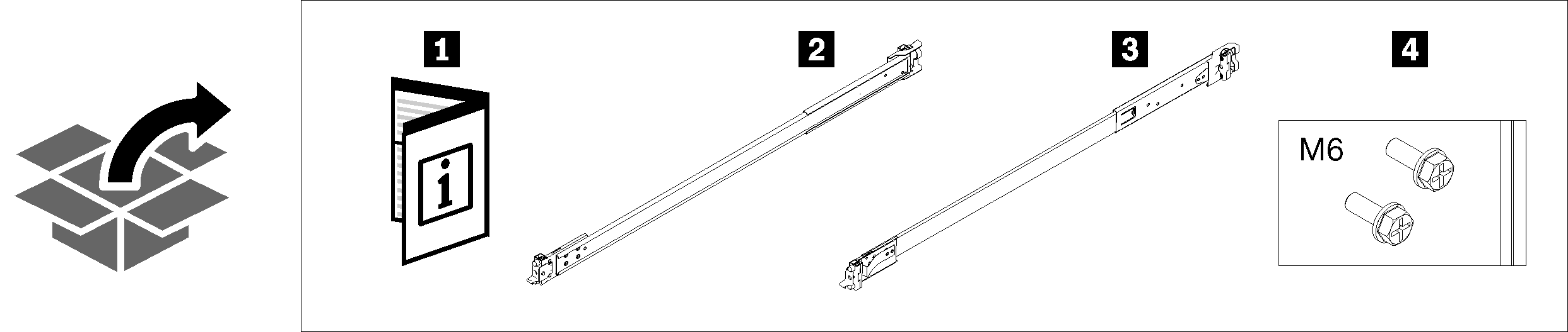
The cabinet supports up to four units of rail kit and SE350 E1 Enclosure and corresponding rail kit. For optimal use of space, it is advised to determine the location to install the rail kits based on the number of units that are installed.
| 1 Document | 3 Right rail |
| 2 Left rail | 4 Two M6 screws |
One unit: 3U
Two units: 3U and 4U
Three units: 3U, 4U, and 5U
Four units: 3U, 4U, 5U, and 6U
Note
When installed vertically into this cabinet, the server can be installed with server top facing either right or left. In this section, however, it is illustrated with the top of server facing right as an example.
Procedure
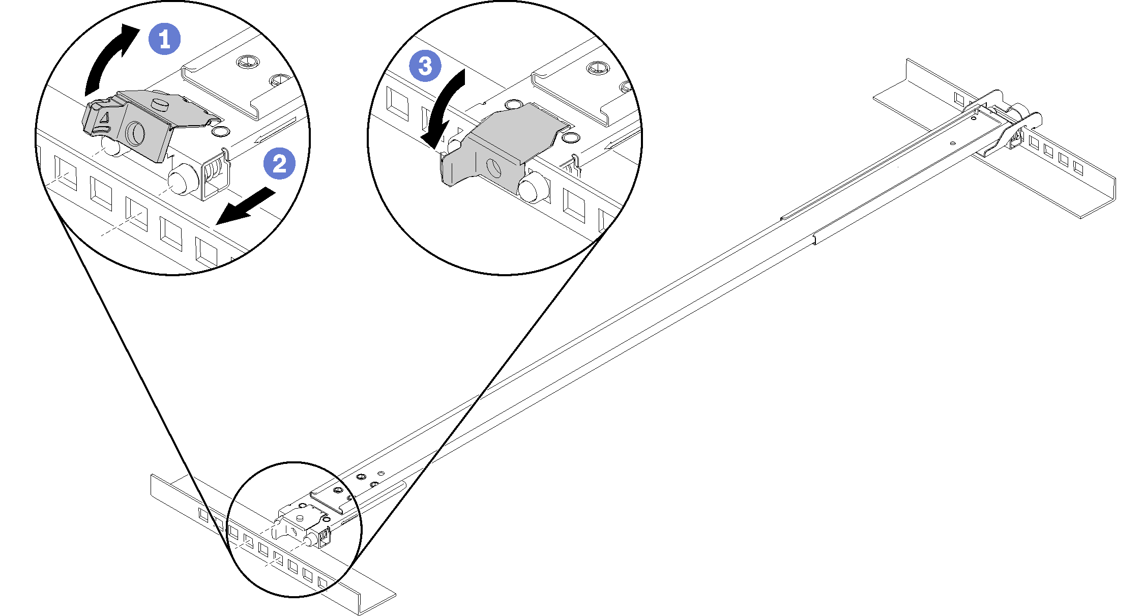
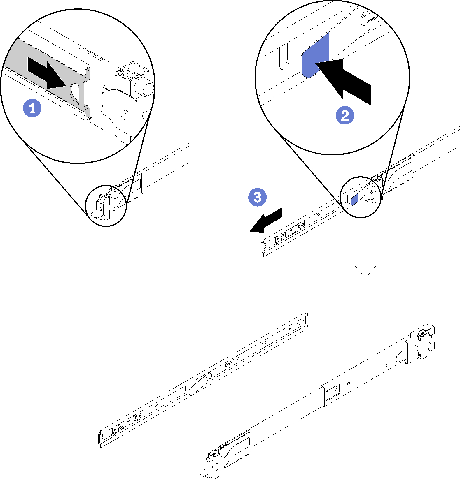
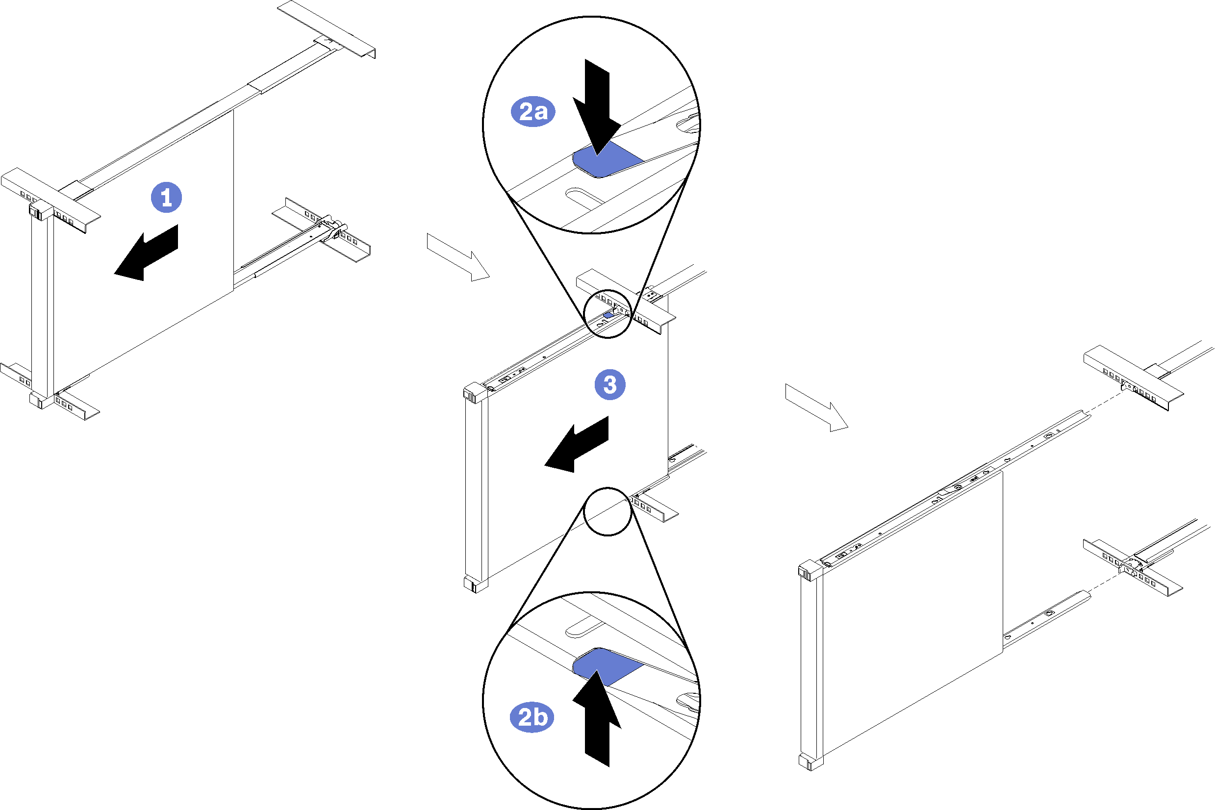
- Remove the inner rails.Figure 1. Removing the inner rails
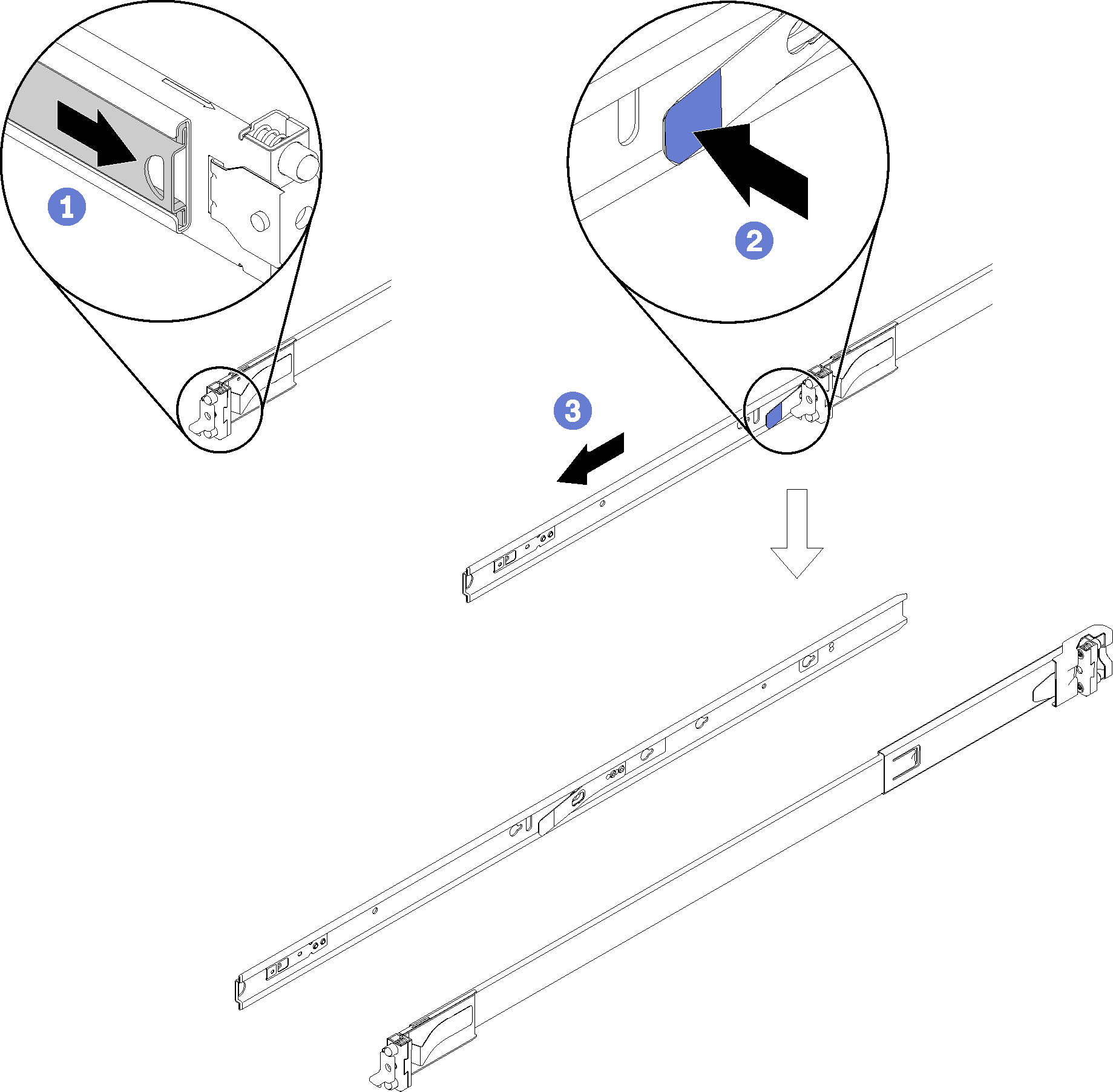
- ① Pull the inner rail outward until the release latch becomes visible.
- ② Press on the release latch.
- ③ Remove the inner rail from the outer rail.
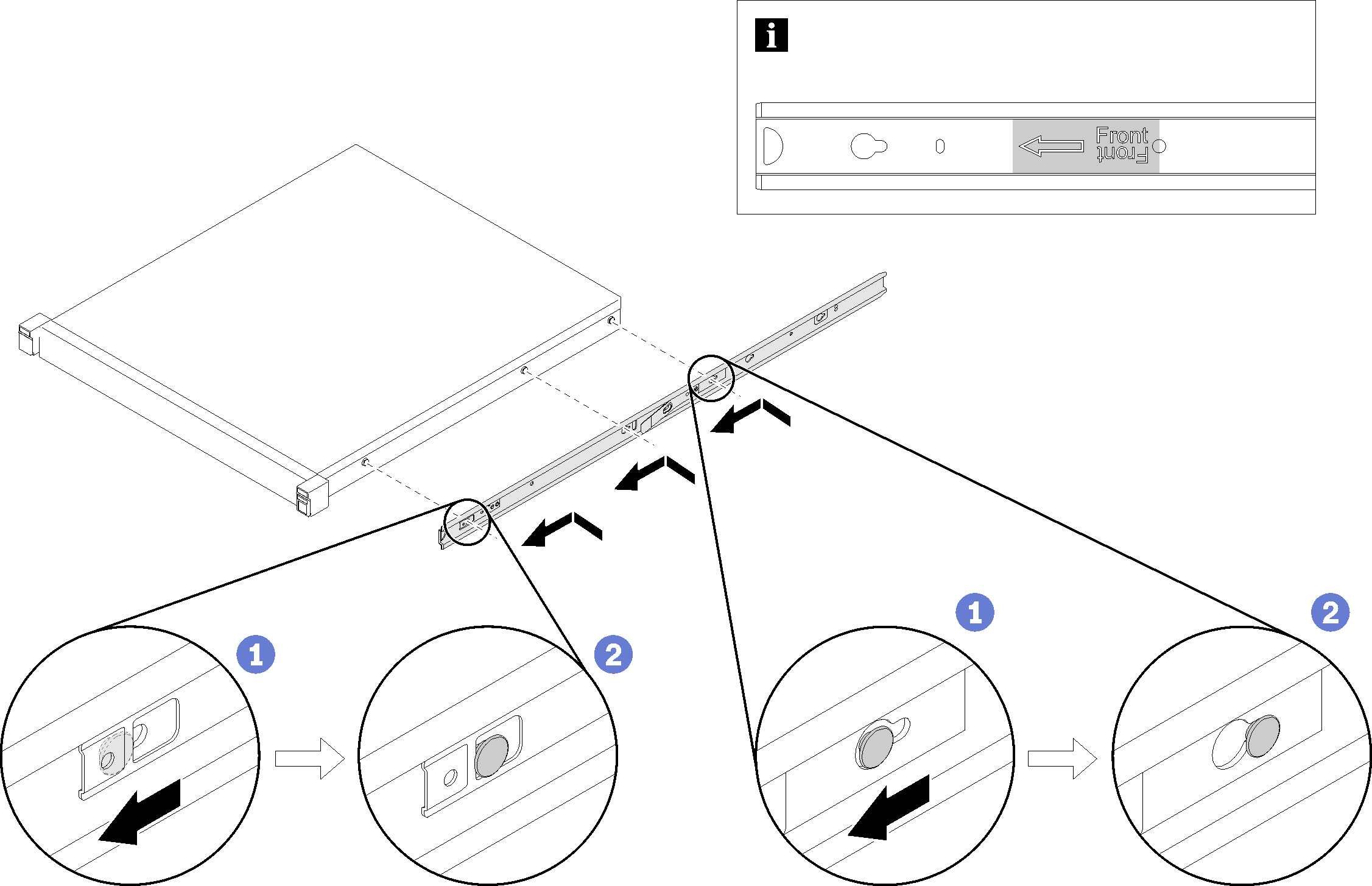
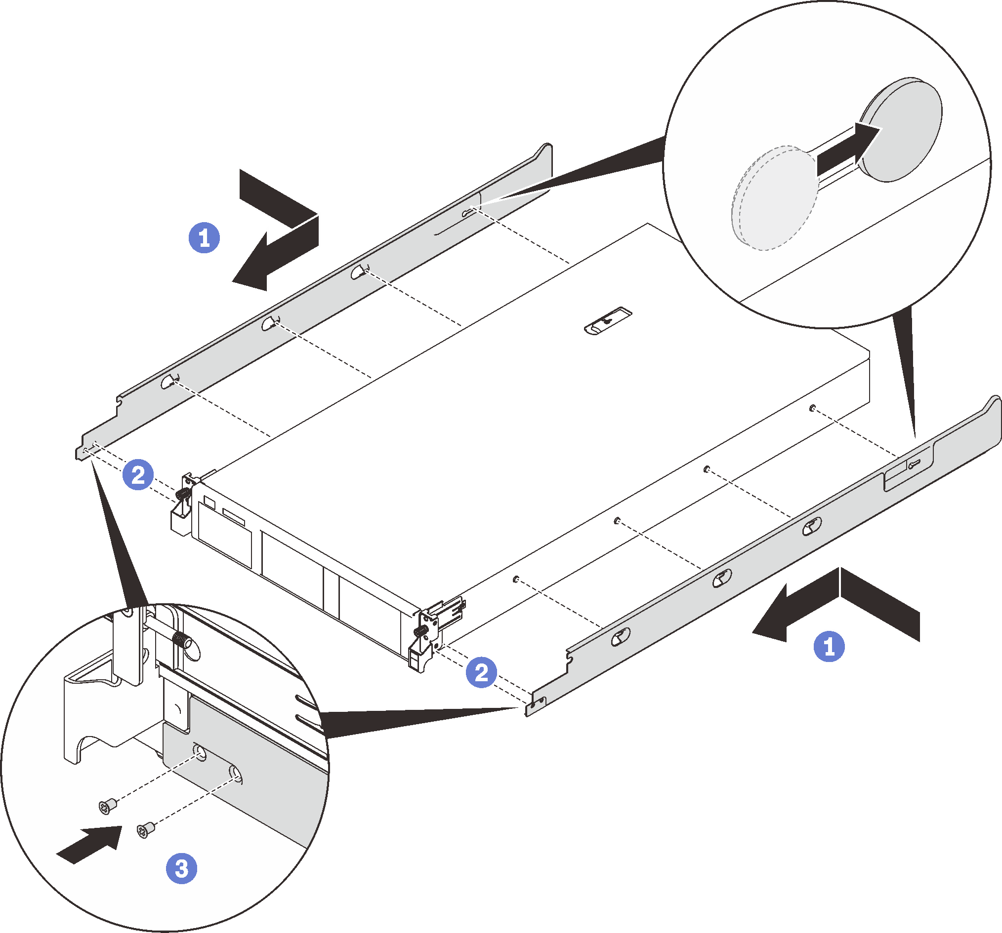
- Install the inner rails to the enclosure.Figure 2. Installing the inner rails to the enclosure
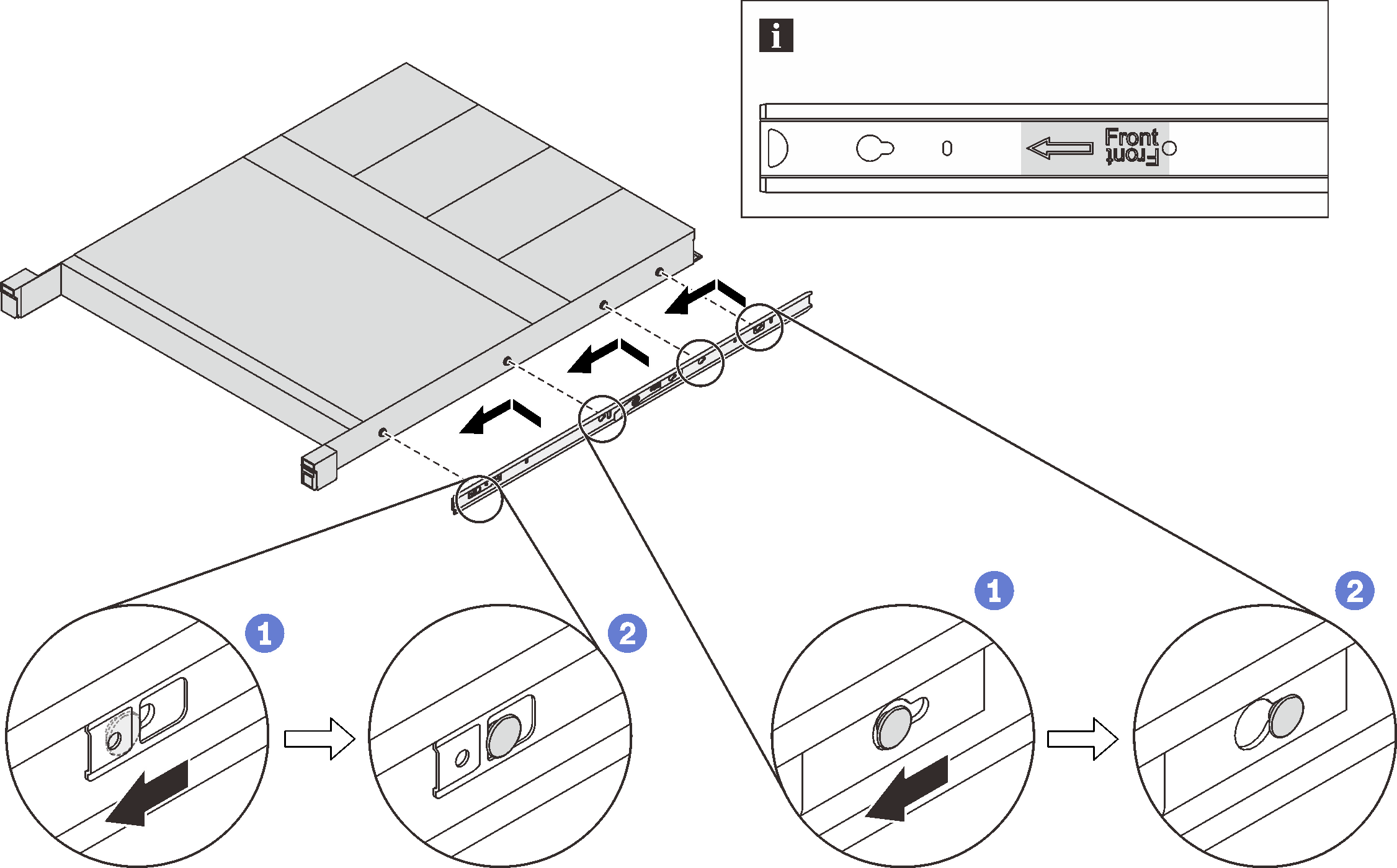
- ① Align the mounting holes in the inner rail with the corresponding rail mounting pins on the side of the enclosure.
- ② Push the inner rail as shown until the mounting pins on the enclosure lock into place with the inner rail.
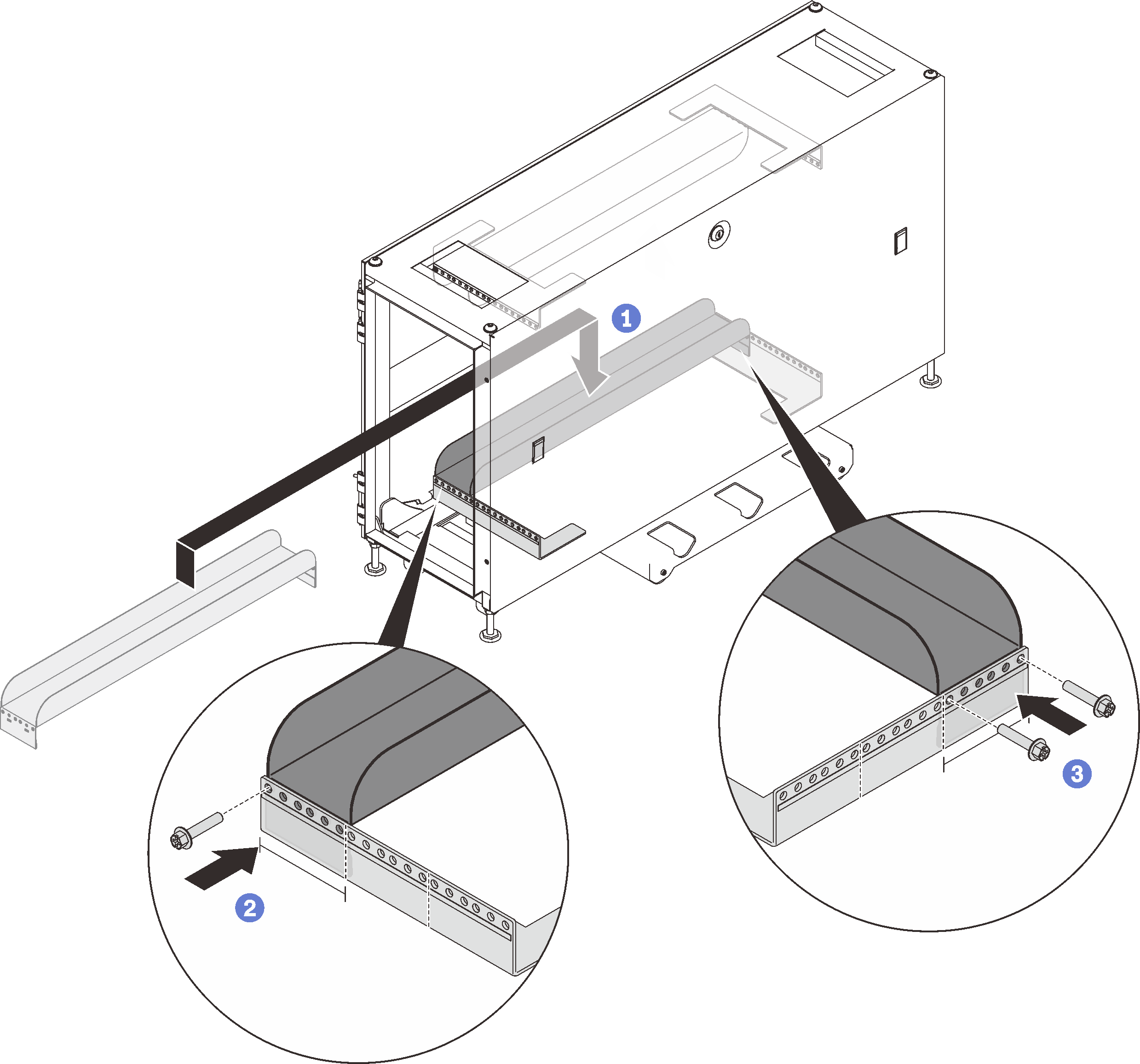
NoteMake sure the stamp “Front” always faces toward the front when assembling the inner rail to the enclosure. - Install the rear mounting bracket of the right outer rail to the lower EIA flange.Figure 3. Installing the rear mounting bracket to the EIA flange
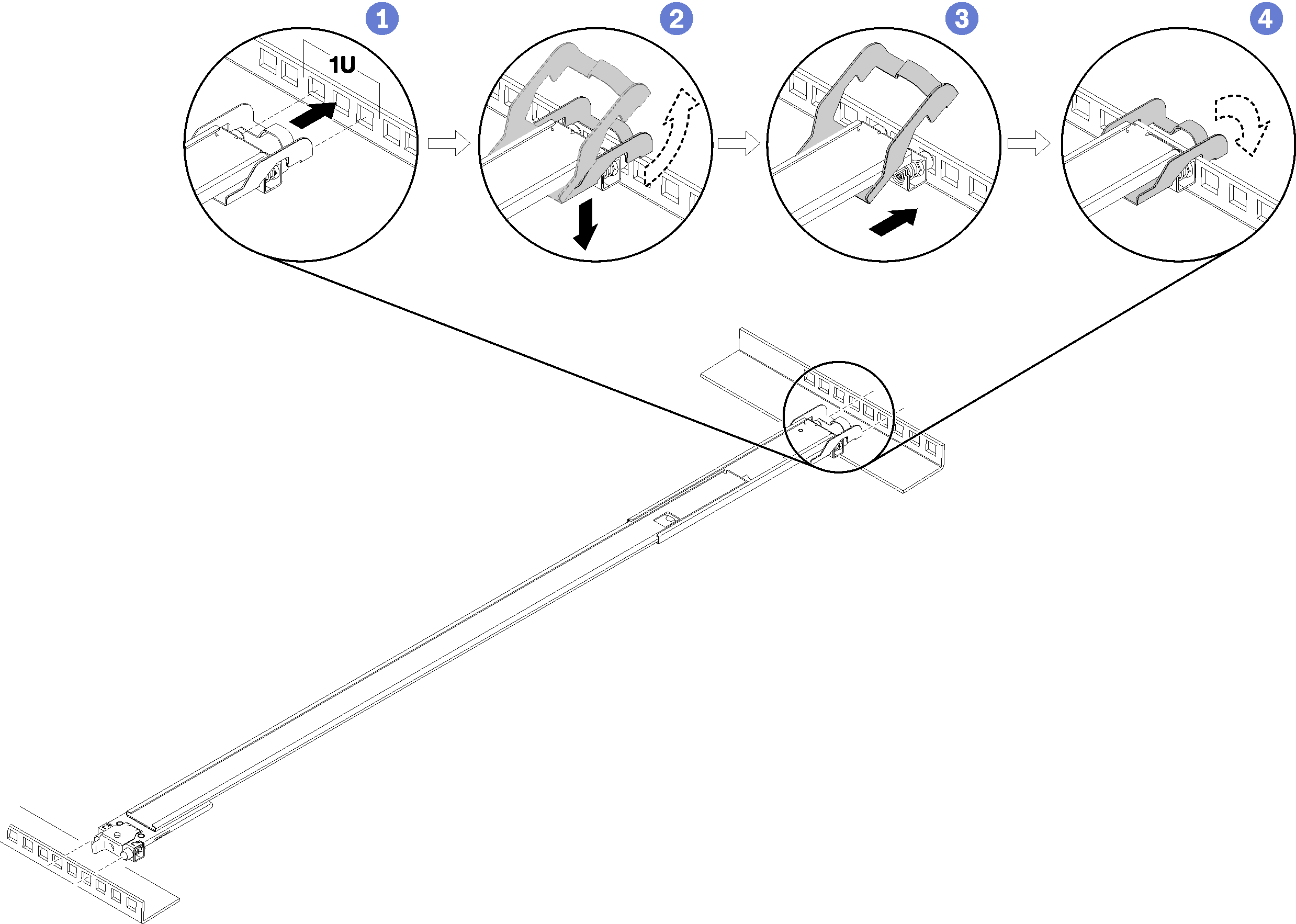
- ① Align the rear pins on the outer rails to the EIA flange.
- ② Slightly push the end of the rail down to hook the rear mounting bracket latch to the rack.
- ③ Push the rail into the EIA flange until the pins protrude through into the corresponding holes in the rack.
- ④ The bracket will lock into place as illustrated.
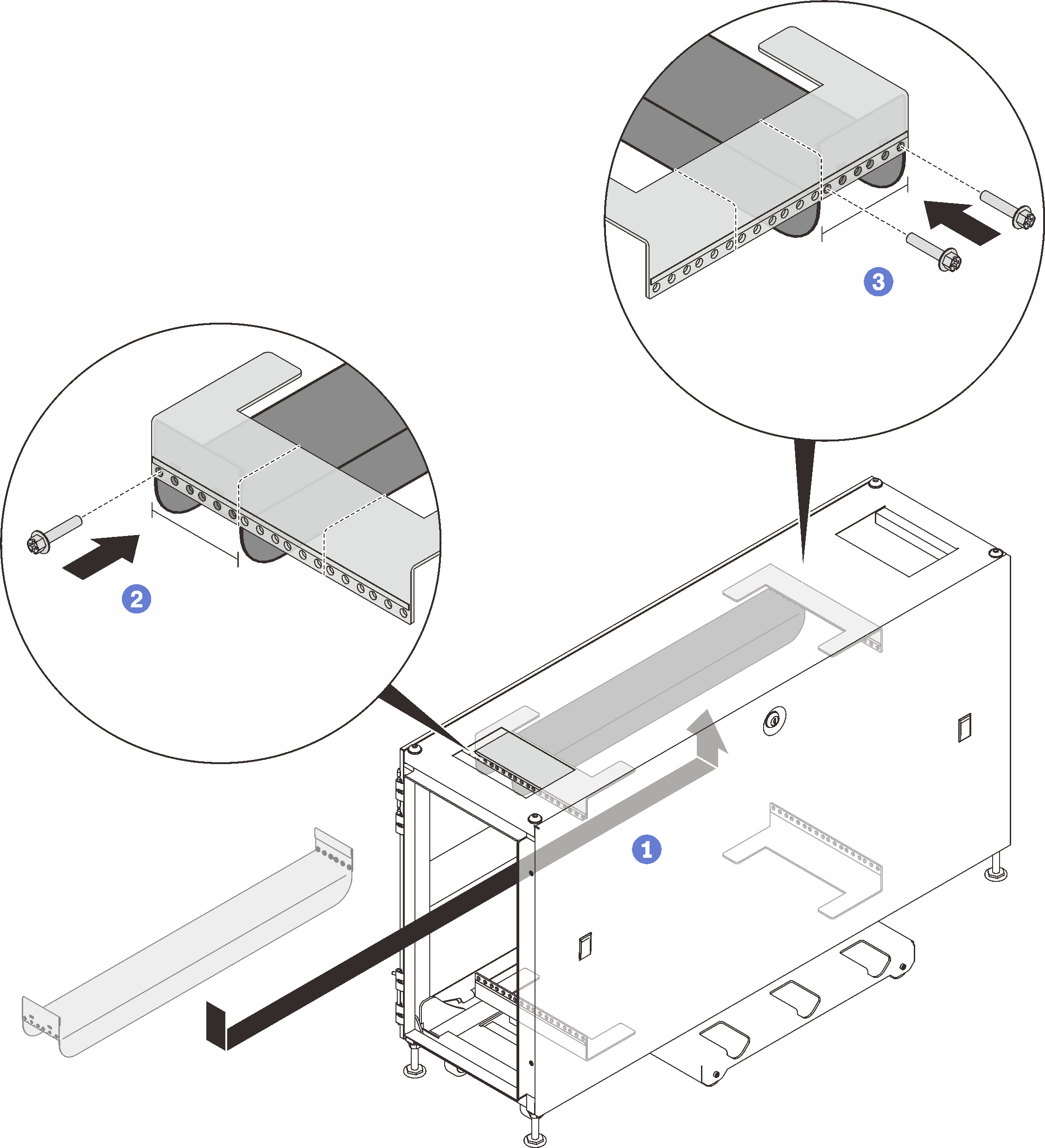
- Install the front mounting bracket of the right outer rail to the lower mounting flange.Figure 4. Installing the front mounting bracket to the EIA flange
 NoteMake sure the rail stays horizontal.
- ① Open the front bracket and align the front end of the outer rail to the EIA flange.
- ② Pull the outer rail into the EIA flange until the pins are inserted into the corresponding holes.
- ③ Close the front bracket to secure the rail.
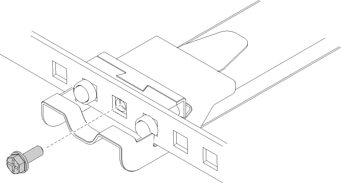
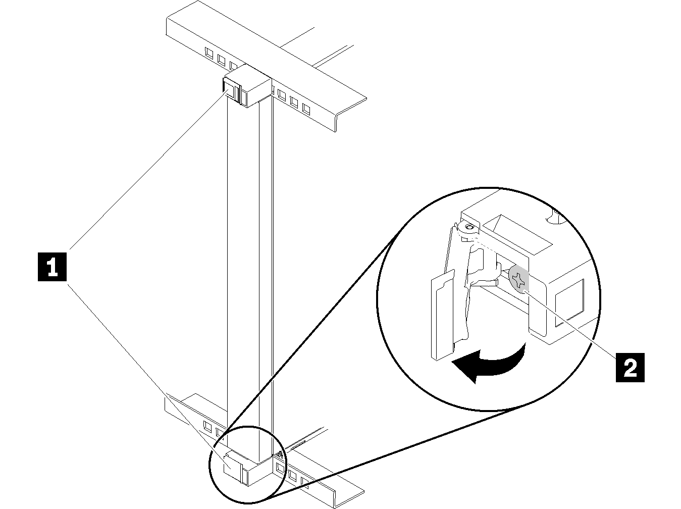
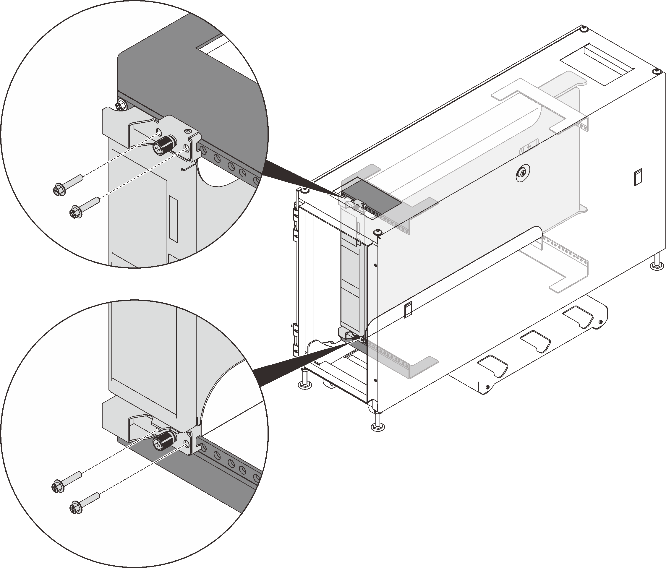
- (Optional) If you need to ship the rack cabinet with the enclosures installed or place the rack cabinet in a vibration-prone area, install two M6 screws into the mounting flanges between the two rear pins on both sides.Figure 5. Installing the rear screws
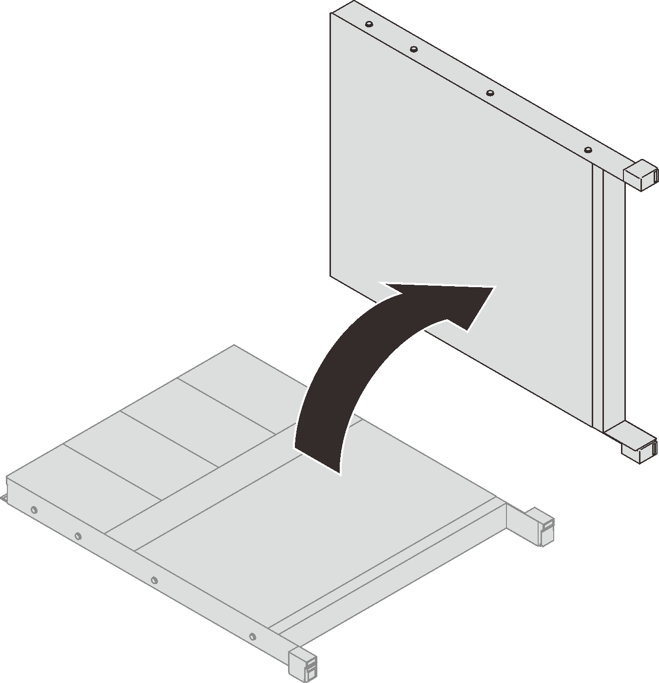
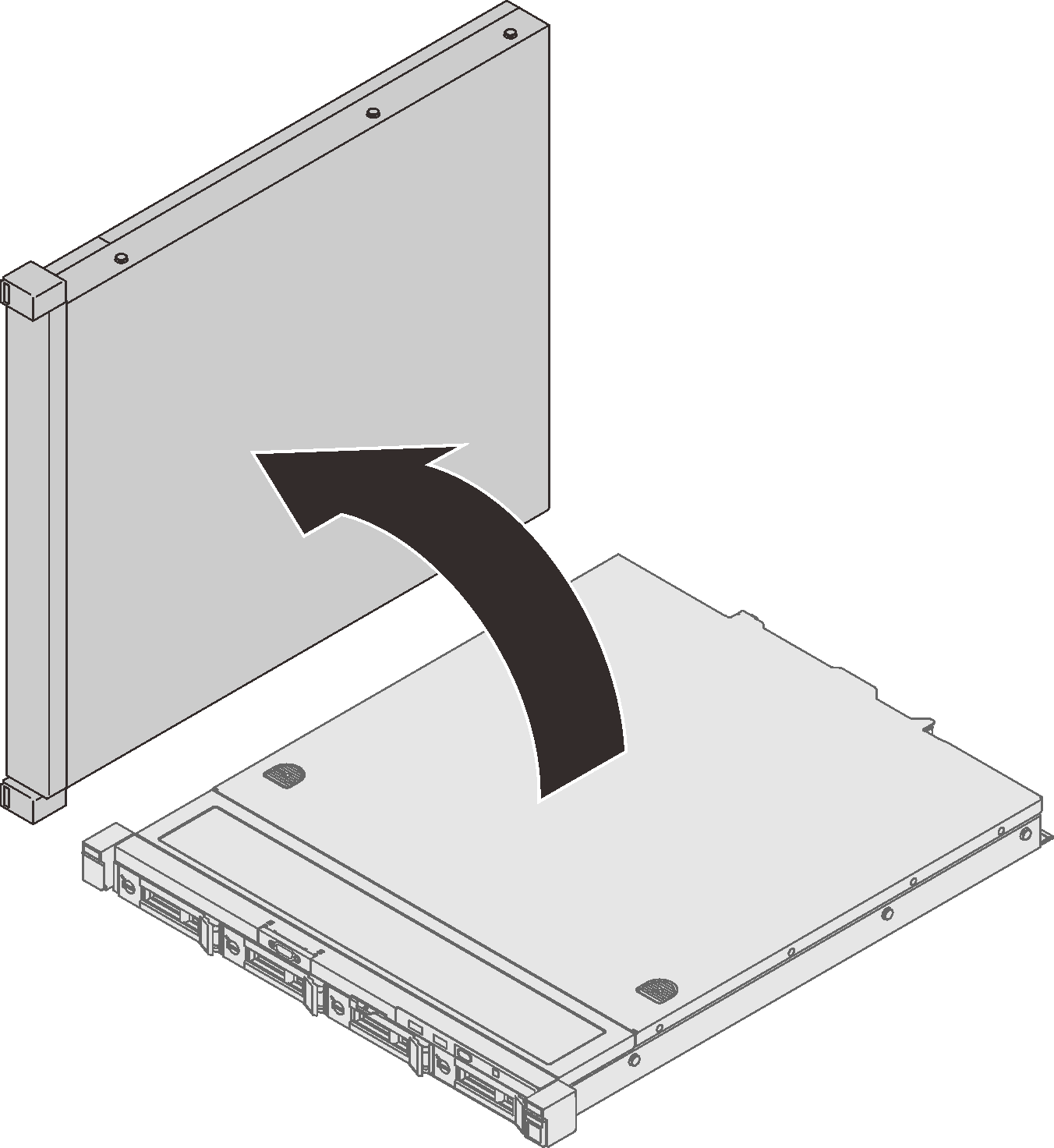
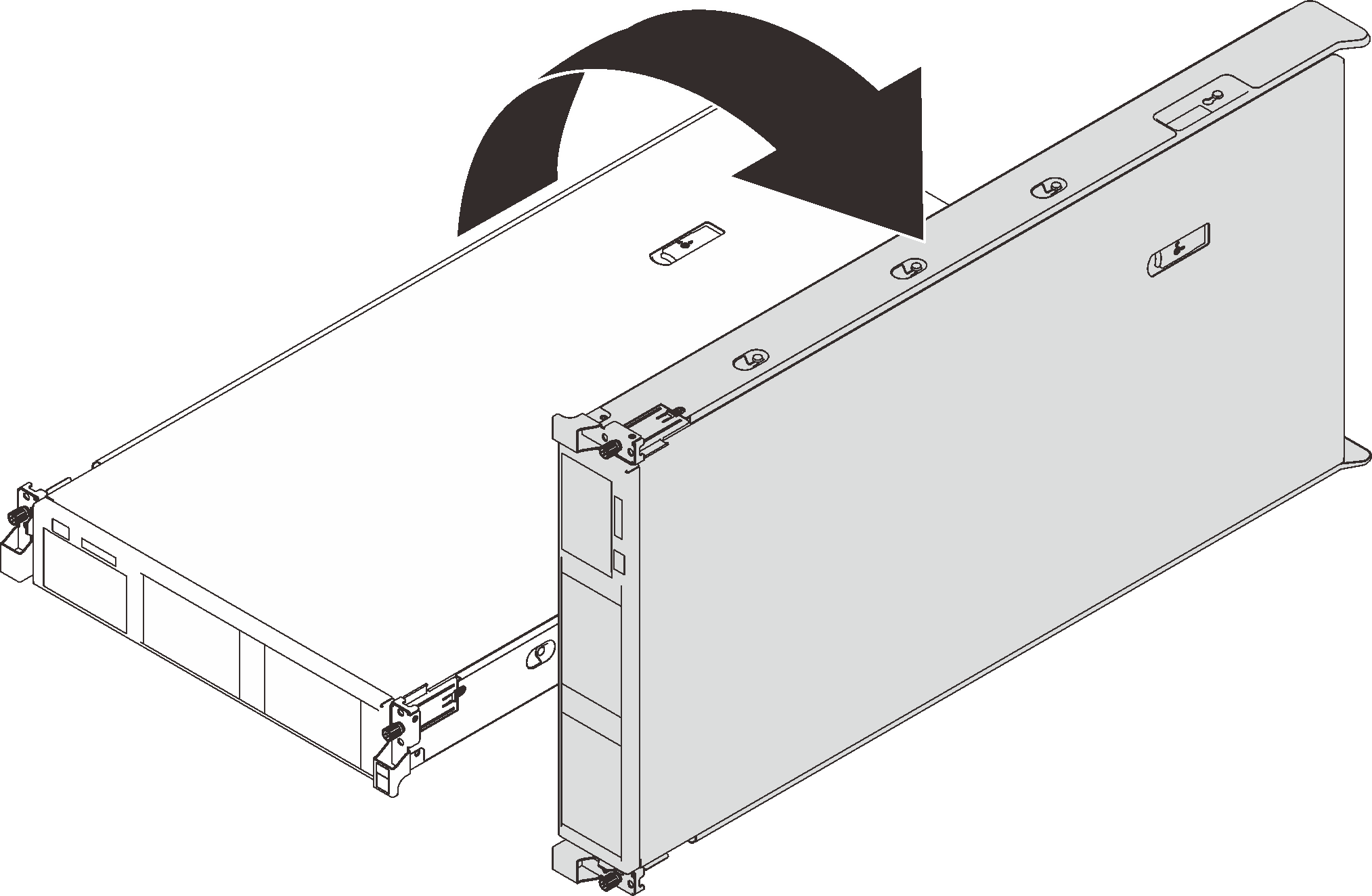
- Rotate the E1 enclosure clockwise so that the right side is facing down. Have one person hold on the front side, while the other hold on the rear side.Figure 6. Rotating SE350 E1 Enclosure
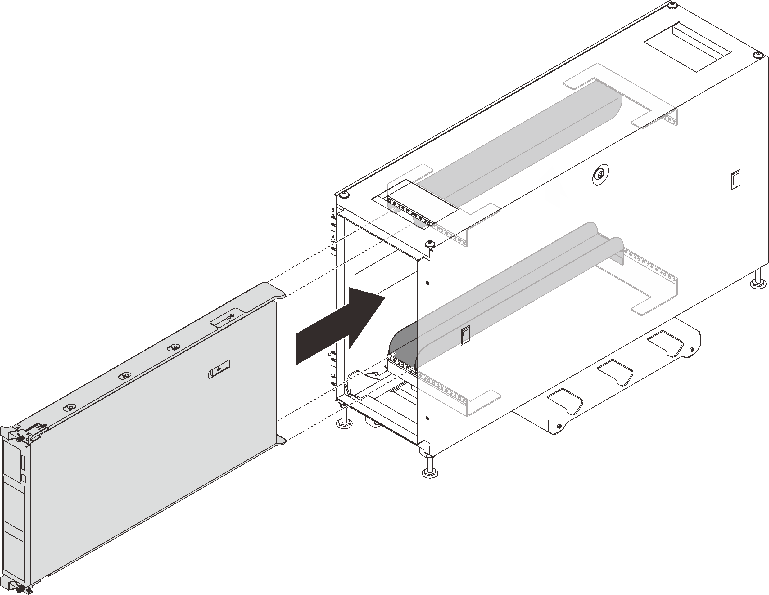
- Install the E1 Enclosure into the rack.Figure 7. Slide the E1 Enclosure into the rails in the rack.
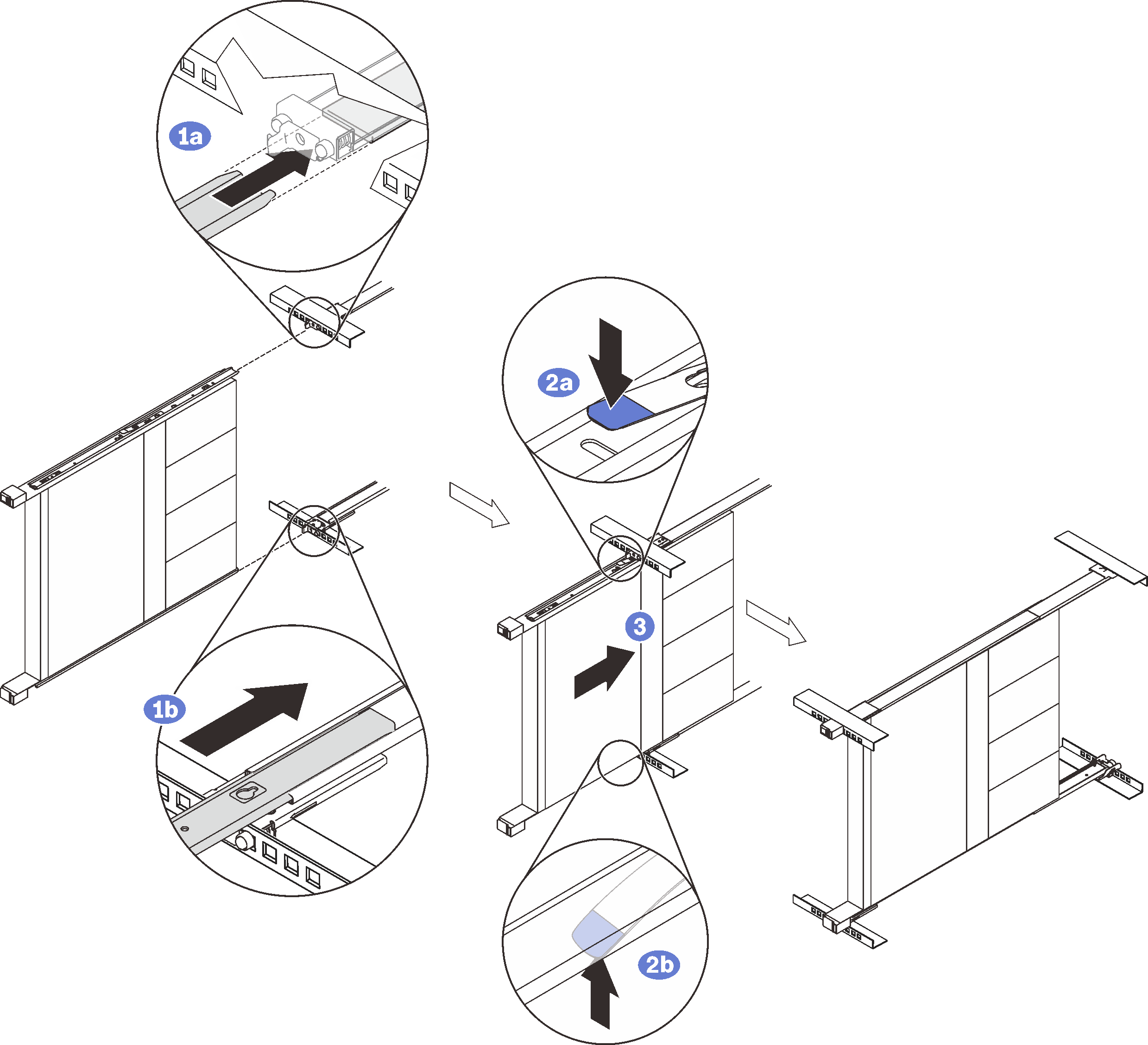 NoteMake sure the top of the enclosure is facing right.
- ① Have the person on the front side support the weight, while the other person on the rear side align the enclosure to the slide rails. Position the enclosure as shown, and slide it into the rack.
- ② Press the release latches.
- ③ Push the enclosure all the way into the rack until it clicks into locked position.
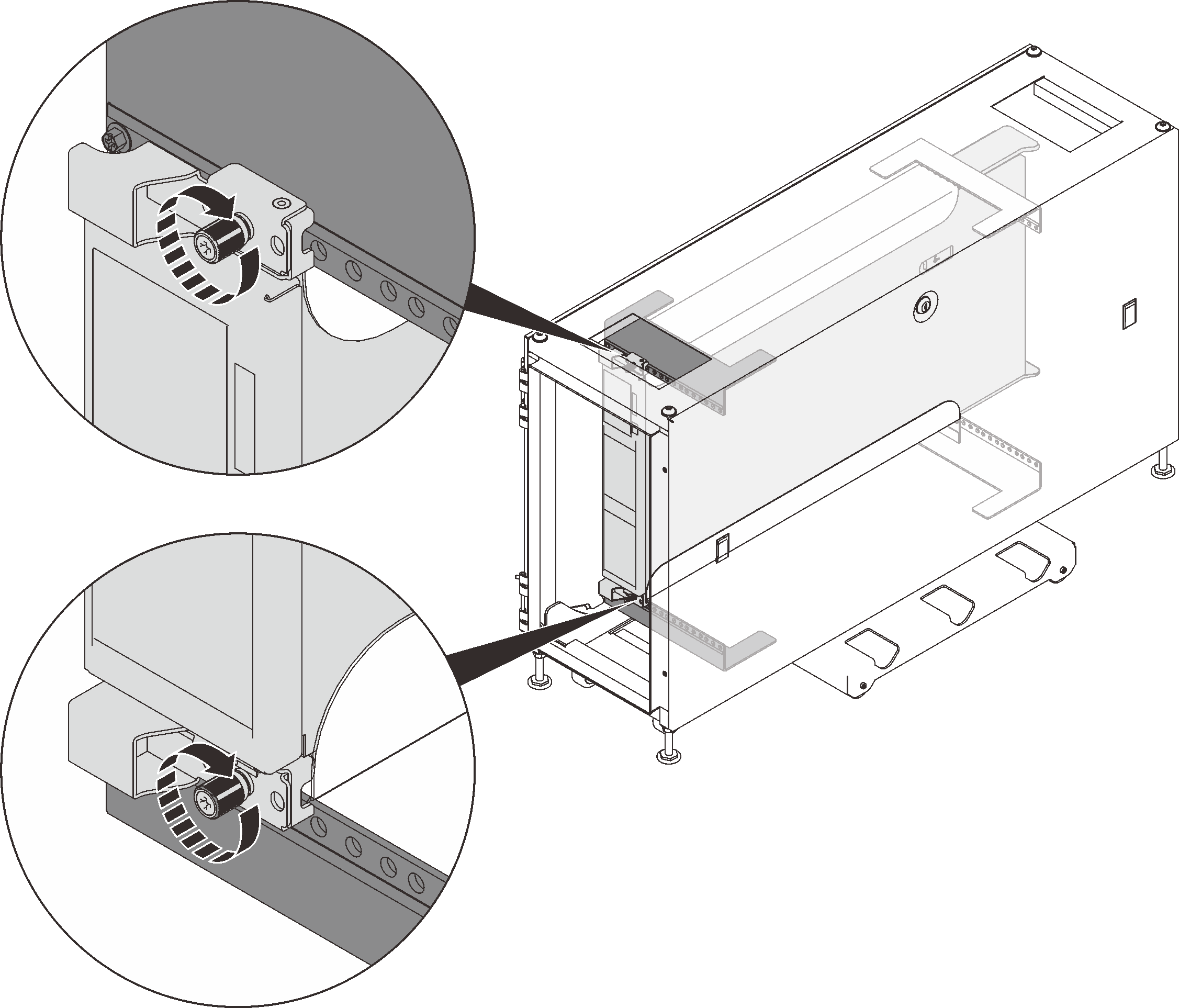
- (Optional) Open the rack release latches and tighten the screws to firmly secure the rail before moving or placing the rack cabinet in a vibration-prone area.Figure 8. Securing the enclosure
1 Rack release latches 2 Front screw
Remove SE350 E1 enclosure from the rack
Figure 9. Removing SE350 E1 enclosure
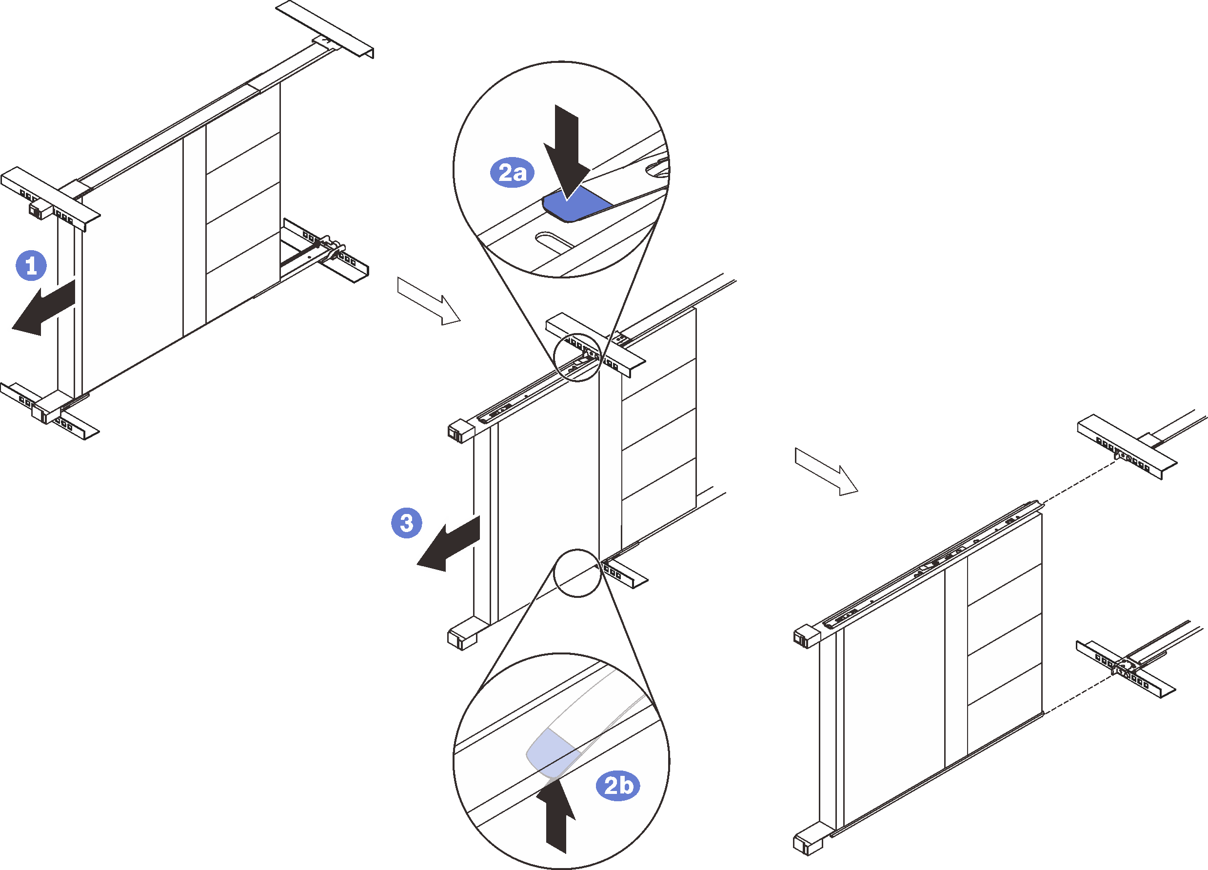
- ① Disconnect all the cables that are connected to the enclosure, and slide the enclosure out until it stops.
- ② Press the release latches to disengage the inner rails.
- ③ Have one person hold the front end of the enclosure, while the other person removes the enclosure.
Install the rail kit and SR250
About this task
See the following table to identify the components that come with the rail kit.
The cabinet supports up to four units of rail kit and SE350 E1 Enclosure and corresponding rail kit. For optimal use of space, it is advised to determine the location to install the rail kits based on the number of units that are installed.
| 1 Document | 3 Right rail |
| 2 Left rail | 4 Two M6 screws |
One unit: 3U
Two units: 3U and 4U
Three units: 3U, 4U, and 5U
Four units: 3U, 4U, 5U, and 6U
Note
When installed vertically into this cabinet, the server can be installed with server top facing either right or left. In this section, however, it is illustrated with the top of server facing left as an example.
Procedure
- Remove the inner rails.Figure 10. Removing the inner rails
- ① Pull the inner rail outward until the release latch becomes visible.
- ② Press on the release latch.
- ③ Remove the inner rail from the outer rail.
- Install the inner rails to the server.Figure 11. Installing the inner rails to the enclosure
- ① Align the mounting holes in the inner rail with the corresponding rail mounting pins on the side of the server.
- ② Push the inner rail as shown until the mounting pins on the server lock into place with the inner rail.
NoteMake sure the stamp “Front” always faces toward the front when assembling the inner rail to the server. - Rotate the server counter-clockwise so that the left side is facing down.Figure 12. Rotating SR250
- Install the rear mounting bracket of the right outer rail to the lower EIA flange.Figure 13. Installing the rear mounting bracket to the EIA flange
- ① Align the rear pins on the outer rails to the EIA flange.
- ② Slightly push the end of the rail down to hook the rear mounting bracket latch to the rack.
- ③ Push the rail into the EIA flange until the pins protrude through into the corresponding holes in the rack.
- ④ The bracket will lock into place as illustrated.
- Install the front mounting bracket of the right outer rail to the lower mounting flange.Figure 14. Installing the front mounting bracket to the EIA flangeNoteMake sure the rail stays horizontal.
- ① Open the front bracket and align the front end of the outer rail to the EIA flange.
- ② Pull the outer rail into the EIA flange until the pins are inserted into the corresponding holes.
- ③ Close the front bracket to secure the rail.
- (Optional) If you need to ship the rack cabinet with servers installed or place the rack cabinet in a vibration-prone area, install two M6 screws into the mounting flanges between the two rear pins on both sides.Figure 15. Installing the rear screws
- Slide the SR250 into the rack:Figure 16. Slide the SR250 into the rack.
 NoteMake sure the top of the enclosure is facing right.
- ① Lift and align the server to the slide rails. Position the enclosure as shown, and slide it into the rack.
- ② Press the release latches.
- ③ Push the enclosure all the way into the rack until it clicks into locked position.
- (Optional) Open the rack release latches and tighten the screws to firmly secure the rail before moving or placing the rack cabinet in a vibration-prone area.Figure 17. Securing the server
1 Rack release latches 2 Front screw
Remove SE350 or SR250 from the rails
Complete the following steps to remove SE350 or SR250 from the rails.
Remove the server from the rack
Figure 18. Removing SR250
- ① Disconnect all the cables that are connected to the server, and slide the server out until it stops.
- ② Press the release latches to disengage the inner rails.
- ③ Remove the server.
Install the rail kit and SR670
About this task
The cabinet supports up to two units of SR670 and corresponding rail kit. For optimal use of space, it is advised to determine the location to install the rail kits based on the number of units that are installed. See the following table to identify the components that come with the mounting kit.
One unit: 1-3U
Two units: 1-3U and 4-6U
Note
- The left and right mounting glides are part of the fire enclosure. Therefore, ensure the glides are installed before attempting to mount the server in vertical orientation.
- Two people are required for this task.
- When installing SR670 in the rack cabinet, do not mix it with SE350 or SR250 in the same cabinet.
| 1 Two C-channels | 4 Four black M3.5 x 5 mm flat head screws with pre-applied threadlocking adhesive |
| 2 One left mounting glide | 5 Ten black M5 x 20 mm combination head screws |
| 3 One right mounting glide |
- Remove the two screws that secure the lower portion of SR670 rack mounting brackets on both sides, and dispose the screws.Figure 19. Removing screws from the rack mounting brackets
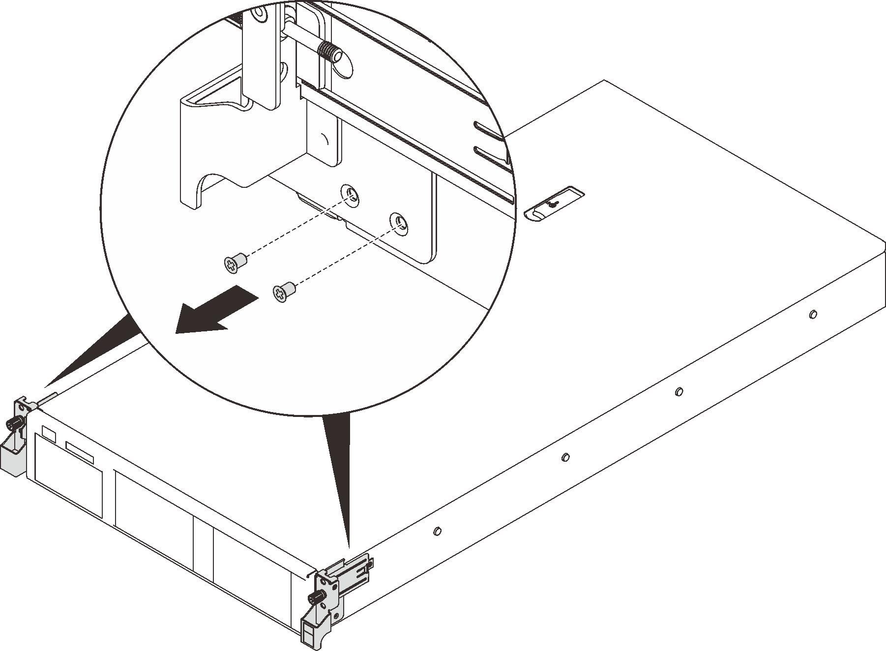 NoteDo not fully remove the rack mounting brackets as they are required to secure the server into the vertical rack.
 - Secure the mounting glides to the server.Figure 20. Securing the mounting glides
- ① Align the key hole slots in the glides to the T-head pins on both sides of the server, and slide the mounting glides forward until the pins are secured in the slots.
- ② Align the two holes on the mounting glide to the threaded standoffs on the front end of the server.
- ③ Secure each mounting glide with two of the M3.5 x 5 mm screws with pre-applied adhesive that come with the vertical mounting kit.
- Install one C-channel in the lower portion of the rack cabinet.Figure 21. Installing the lower C-channel
- ① Align the C-channel between the lower rack EIA flanges.
- ② Secure the front end of the C-channel to the front EIA flange with one M5 x 20 mm screw through the left most hole in the channel.
- ③ Secure the rear end of the C-channel to the rear EIA flange with two M5 x 20 mm screws through the right and left most holes in the bracket.
AttentionDo NOT over-tighten the screws as the rack EIA flange could be deformed. - Install the other C-channel in the upper portion of the rack cabinet.Figure 22. Installing the upper C-channel
- ① Have one person hold and align the C-channel between the upper rack EIA flanges.
- ② Secure the front end of the C-channel to the front EIA flange with one M5 x 20 mm screw through the left most hole in the channel.
- ③ Secure the rear end of the C-channel to the rear EIA flange with two M5 x 20 mm screws through the right and left most holes in the bracket.
- Rotate the server 90 degree clockwise so that the right side is facing down.Figure 23. Rotating the server
- Lift the server with two people, and slide it into the C-channels.Figure 24. Installing the server into the rack cabinet
- Tighten both the upper and lower captive thumb screws.Figure 25. Securing the rack mounting brackets
- Secure each rack mounting bracket with two M5 x 20 mm screws.Figure 26. Securing the rack mounting brackets
フィードバックを送る