GPU node cable routing
Use this information to route the cables for SD650-I V3 trays.
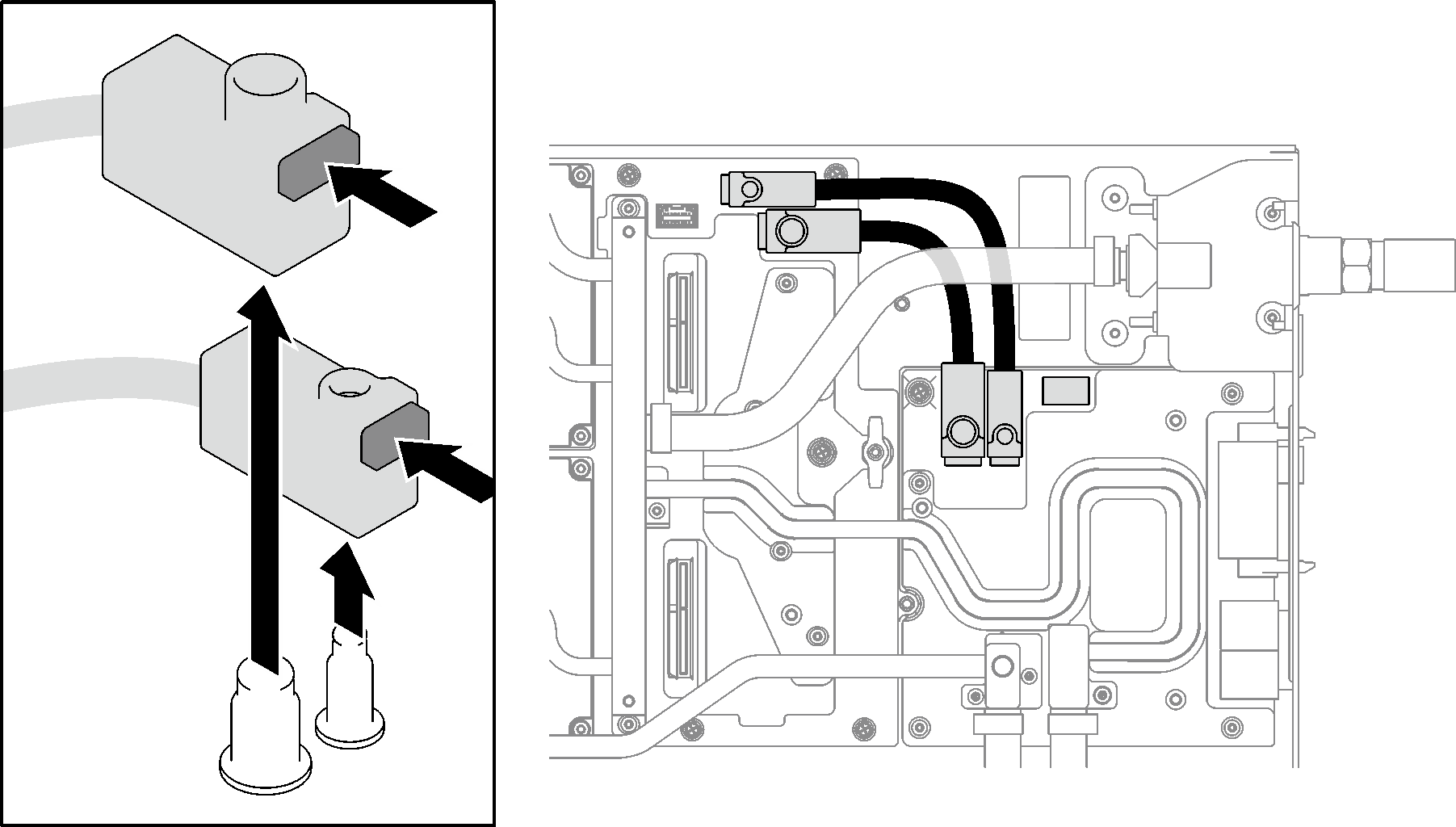
SD650-I V3 tray power cables
Press the latch on the power cable connector remove the cables from the GPU node.
Figure 1. Power cable connector
SD650-I V3 tray power cable routing
Figure 2. SD650-I V3 tray power cable routing
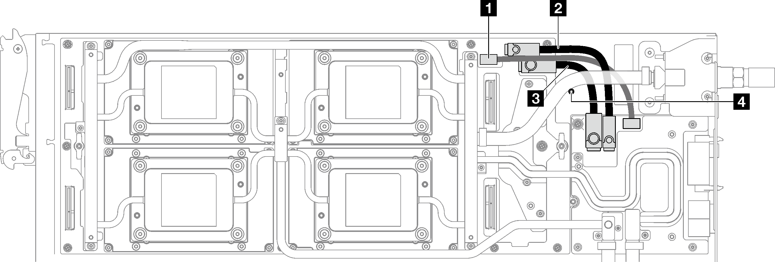
| Component | From (carrier base board) | To (GPU power distribution board) |
|---|---|---|
| Side band cable | 1 Sideband cable connector | 1 Sideband cable connector |
| 48V power cable | 2 48V power cable connector | 2 48V power cable connector |
| Ground cable | 3 Ground cable connector | 3 Ground cable connector |
| 4 Tall stand off. Route the water loop tube against the tall stand off. | ||
SD650-I V3 tray signal cable routing
Figure 3. SD650-I V3 tray signal cable routing
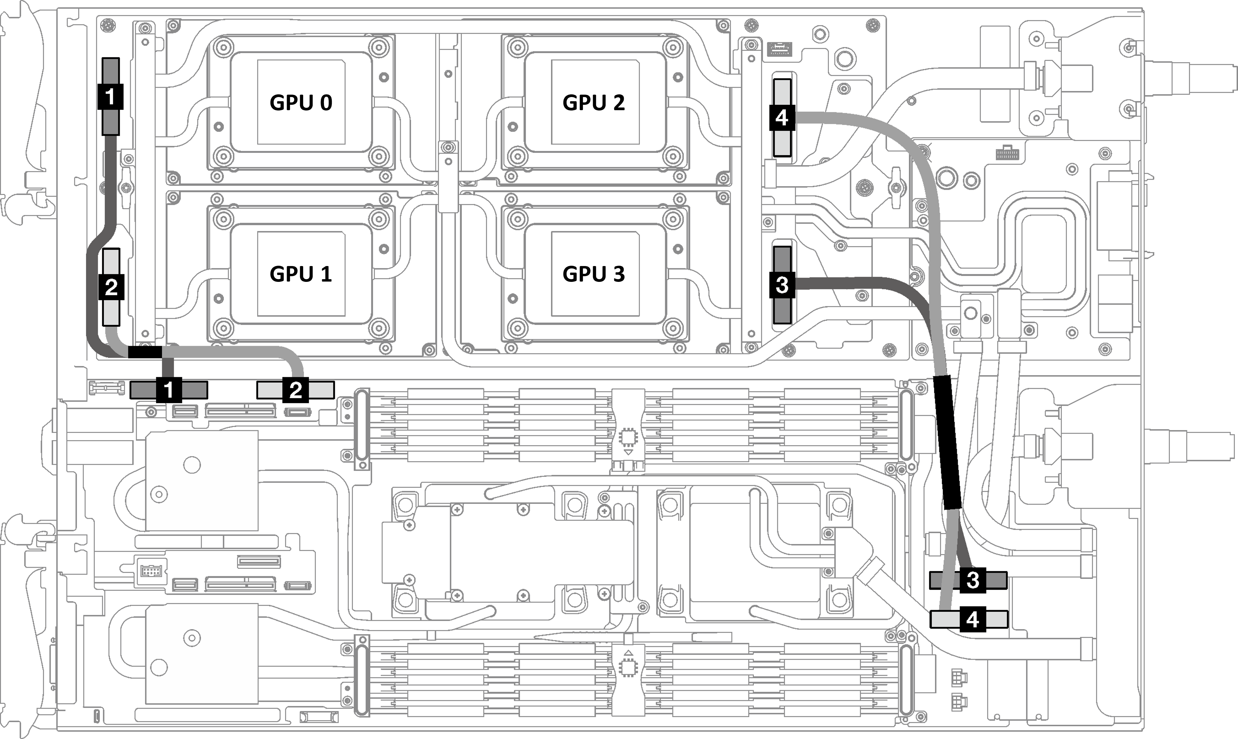
| Compute Node | Retimer cable 0/1 | GPU node | |||||
| Root port | System board silkscreen | Cable connector silkscreen | Carrier base board (CBB) silkscreen | Device ID | |||
| CPU 0 PE 3 | 1 PCIe slot 1 | CONNECTING | PCIE 1 | MCIO 0 | CONNECTING | 1 MCIO 0 connector | OAM 0 |
| CPU 0 PE 2 | 2 PCIe slot 2 | PCIE 2 | MCIO 1 | 2 MCIO 1 connector | OAM 1 | ||
| Compute Node | Retimer cable 2/3 | GPU node | |||||
| Root port | System board silkscreen | Cable connector silkscreen | Carrier base board (CBB) silkscreen | Device ID | |||
| CPU 1 PE 4 | 3 PCIe slot 3 | CONNECTING | PCIE 3 | MCIO 3 | CONNECTING | 3 MCIO 3 connector | OAM 3 |
| CPU 1 PE 3 | 4 PCIe slot 4 | PCIE 4 | MCIO 2 | 4 MCIO 2 connector | OAM 2 | ||
Give documentation feedback