PCIe-Adapterkartenbaugruppe installieren (ConnectX-7 NDR 200)
Mithilfe der Informationen in diesem Abschnitt können Sie eine PCIe-Adapterkartenbaugruppe mit ConnectX-7 NDR 200 Adapter installieren.
Zu dieser Aufgabe
Erforderliche Werkzeuge
Bausatz mit verschiedenen Teilen
CX7 NDR200 Thermo-Kits (nur beschädigte Leitplatte muss ersetzt werden)
ConnectX-7 NDR200 Putty-Pad-Satz
SD650-N V3 2U PCIe-Halterung mit Aussparungen (nur bei Installation eines neuen ConnectX-7 NDR 200 Adapters)
Informationen zur Position und Ausrichtung des Gap-Pads/Putty-Pads finden Sie unter Identifikation und Position von Gap-Pad/Putty-Pad.
Reinigen Sie vor dem Austausch des Gap-Pads/Putty-Pads vorsichtig die Schnittstellenplatte oder Hardwareoberfläche mit einem alkoholhaltigen Reinigungstuch.
Halten Sie das Gap-Pad/Putty-Pad vorsichtig fest, um eine Verformung zu vermeiden. Stellen Sie sicher, dass keine Schraubenlöcher oder Öffnungen durch das Material des Gap-Pads/Putty-Pads verdeckt werden.
Verwenden Sie kein abgelaufenes Putty-Pad. Überprüfen Sie das Verfallsdatum auf der Verpackung des Putty-Pads. Wenn die Putty-Pads abgelaufen sind, kaufen Sie neue, um sie ordnungsgemäß zu ersetzen.
Lesen Sie Installationsrichtlinien und Sicherheitsprüfungscheckliste, um sicherzustellen, dass Sie sicher arbeiten.
Schalten Sie den entsprechenden DWC Einbaurahmen aus, auf dem Sie die Aufgabe ausführen werden.
Ziehen Sie alle externen Kabel vom Gehäuse ab.
Ziehen Sie die QSFP-Kabel von der Lösung ab. Dies erfordert zusätzliche Kraft.
Vorgehensweise
- Wenn Sie einen neuen ConnectX-7 NDR 200-Adapter installieren, ersetzen Sie die Adapterhalterung durch die geschnittene 2U PCIe Halterung.
1 2U PCIe-Halterung mit Aussparungen 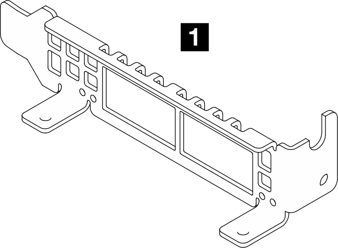
 Entfernen Sie die zwei Schrauben vom Adapter.
 Entfernen Sie die ursprüngliche Halterung vom AdapterAbbildung 1. Entfernen der Originalhalterung vom ConnectX-7 NDR 200
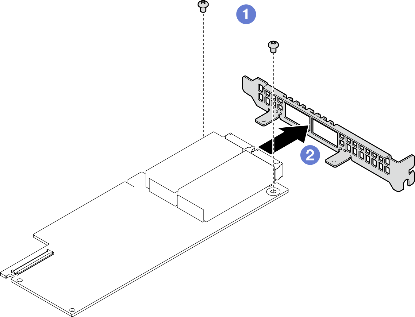
 Installieren Sie die 2U PCIe-Halterung mit Aussparungen am Adapter.
 Ziehen Sie die beiden Schrauben fest, um die Halterung am Adapter zu befestigen.Abbildung 2. Installieren einer angepassten Halterung am ConnectX-7 NDR 200
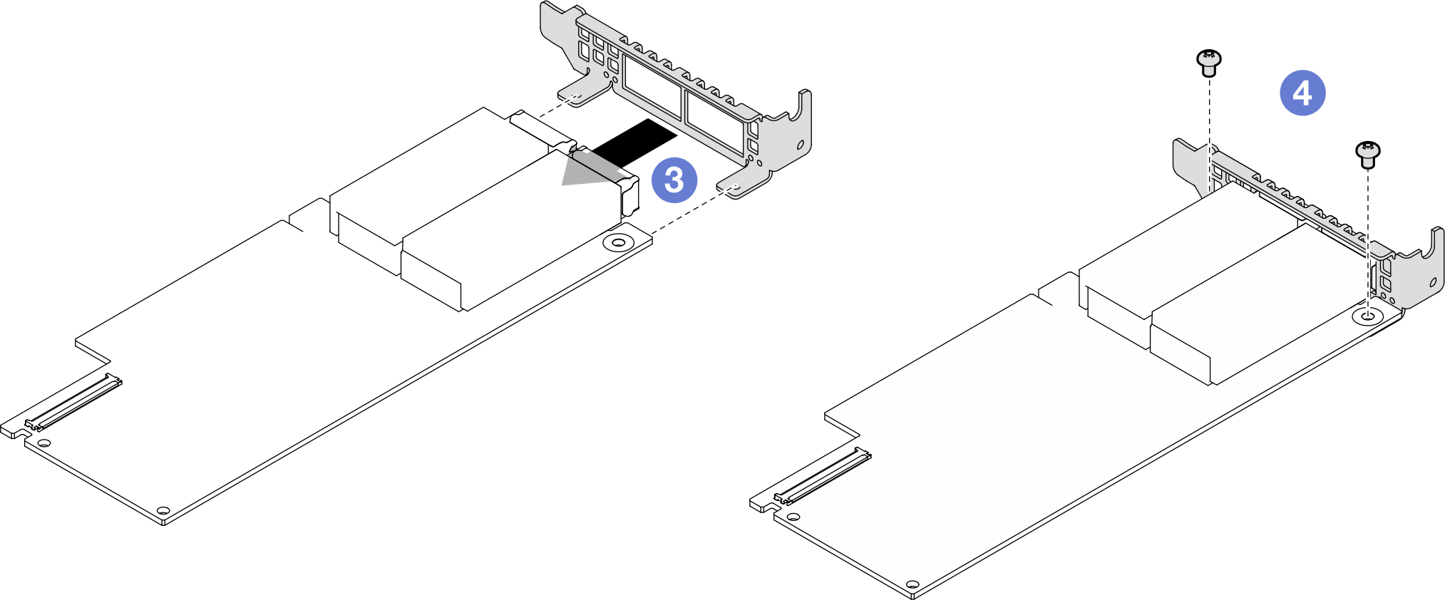
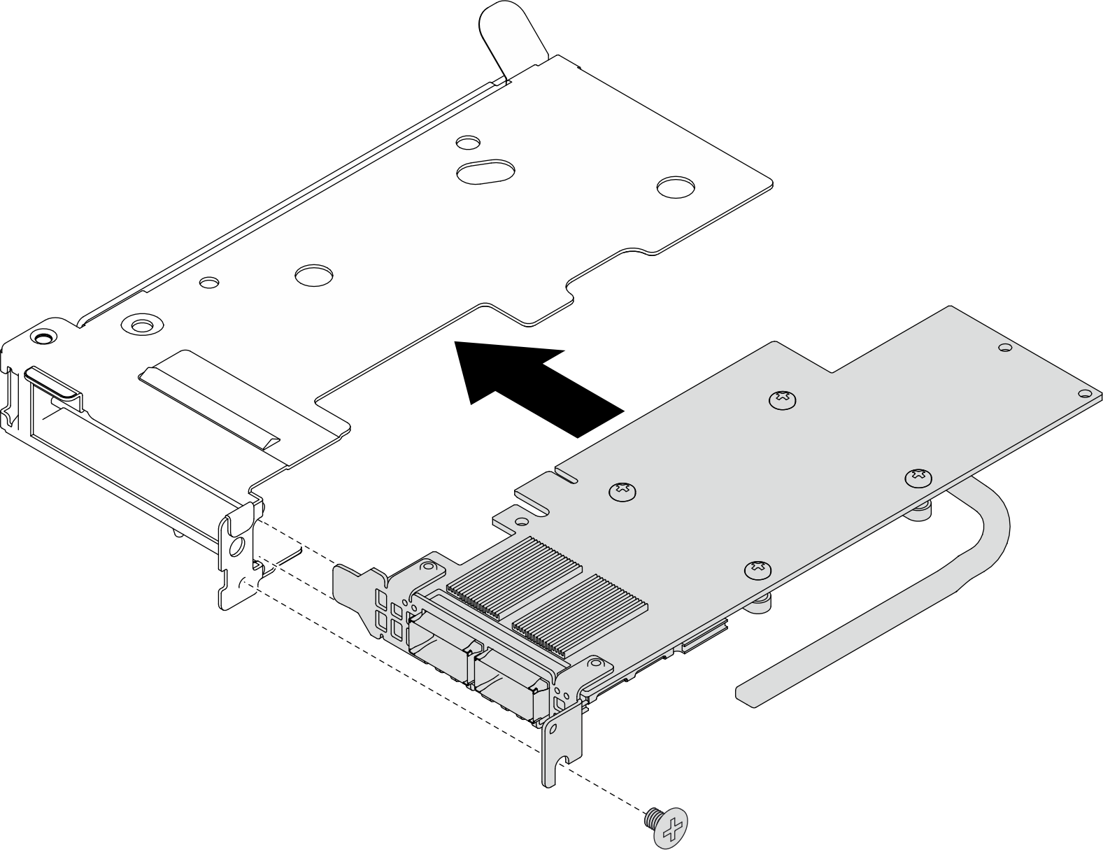
- Installieren Sie den ConnectX-7 NDR 200-Adapter im PCIe-Adapterrahmen. Richten Sie den ConnectX-7 NDR 200 Adapter am PCIe-Steckplatz des Adapterrahmens aus. Drücken Sie dann den Adapter vorsichtig gerade in den Steckplatz, bis er ordnungsgemäß eingesetzt ist. Ziehen Sie die Schraube fest, um den Adapter zu befestigen.Abbildung 3. Installieren des ConnectX-7 NDR 200-Adapters im Adapterrahmen
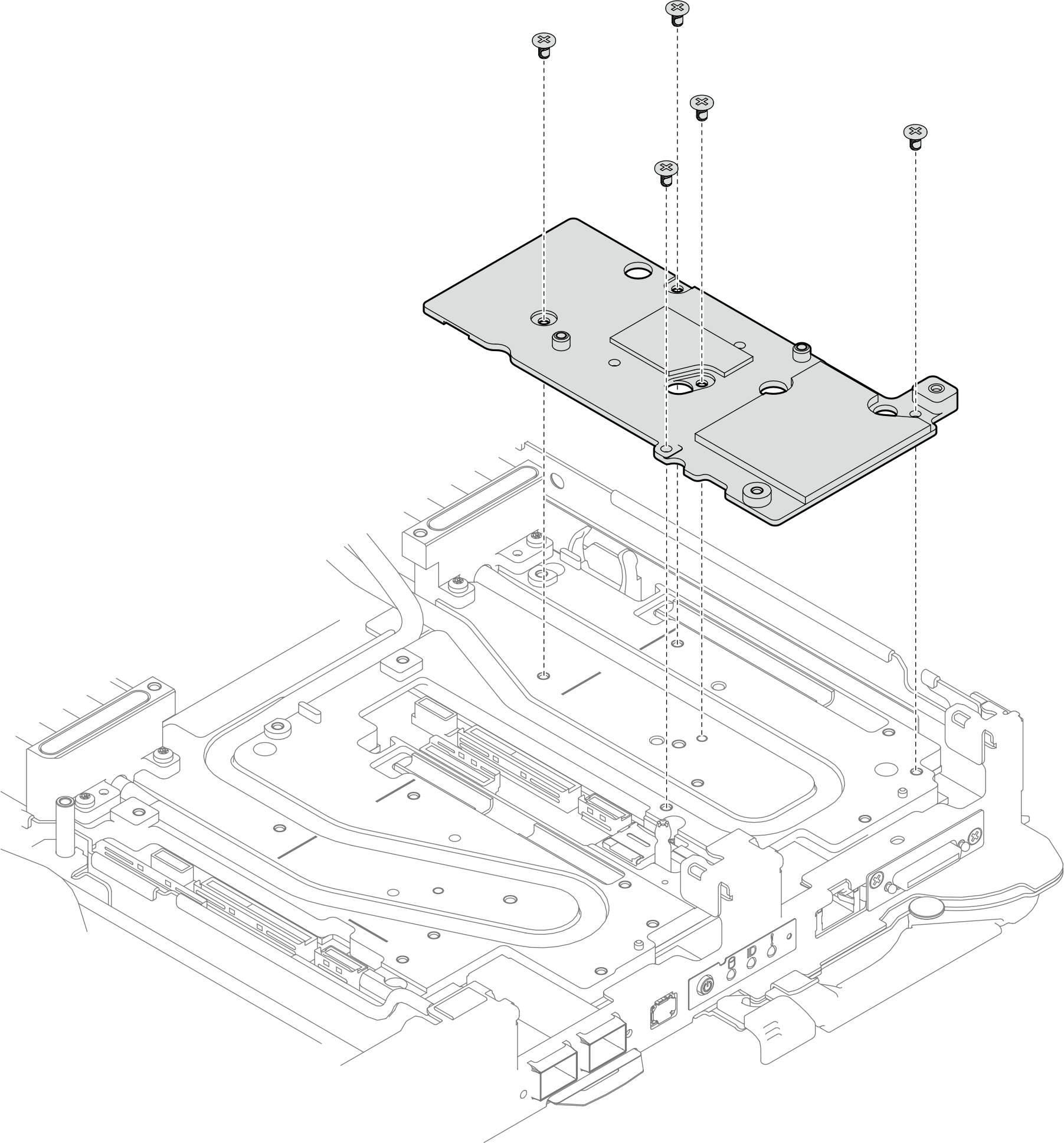
- Wenn die Schnittstellenplatte entfernt wurde, setzen Sie die Schnittstellenplatte auf den Knoten und befestigen Sie sie anschließend mit fünf PH2-Kreuzschlitzschrauben.Abbildung 4. Installation der Schnittstellenplatte
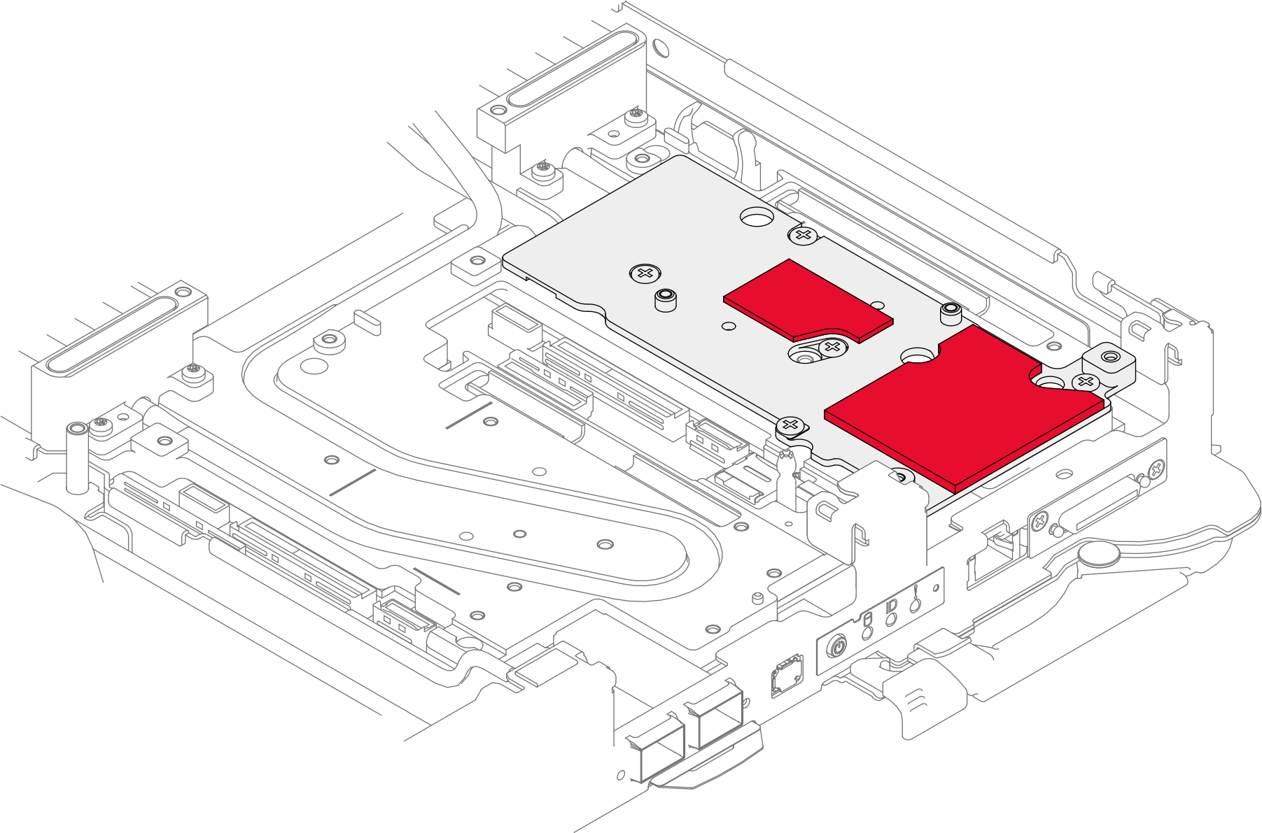
- Ersetzen Sie das Putty-Pad der Schnittstellenplatte durch ein neues. Befolgen Sie unbedingt die Richtlinien zum Austauschen von Gap-Pads/Putty-Pads.Abbildung 5. Schnittstellen-Pad auf Kühlplatte für CX-7 NDR 200
- Installieren Sie die PCIe-Adapterkartenbaugruppe.
- Befestigen Sie einen Sechskant-Abstandsbolzen an der Kühlplatte.
- Richten Sie die Lasche an der PCIe-Adapterkartenbaugruppe am Schlitz vorne am Knoten aus. Setzen Sie die PCIe-Adapterkartenbaugruppe anschließend auf die Systemplatine.
- Befestigen Sie die Adapterkartenbaugruppe mit einer Schraube.
Abbildung 6. PCIe-Adapterkartenbaugruppe installieren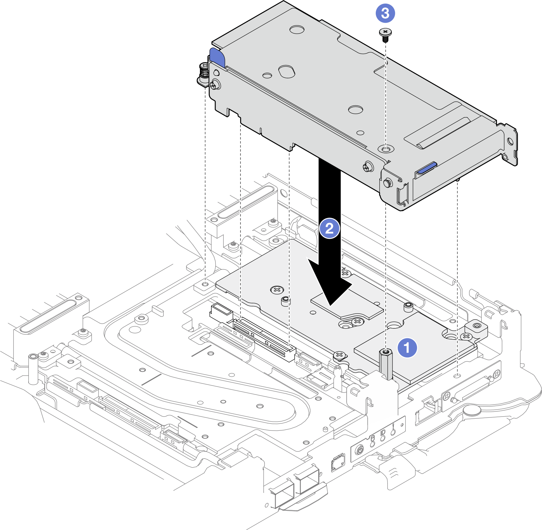
- Befestigen Sie die PCIe-Adapterbaugruppe.
- Bringen Sie die Klemmbefestigung an und ziehen Sie die unverlierbare Schraube an.
- Ziehen Sie die unverlierbare Schraube an der PCIe-Adapterkartenbaugruppe an.
- Befestigen Sie die PCIe-Adapterkartenbaugruppe mit den zwei Schrauben.
Abbildung 7. Installation der unverlierbaren Schraube der Klemmbefestigung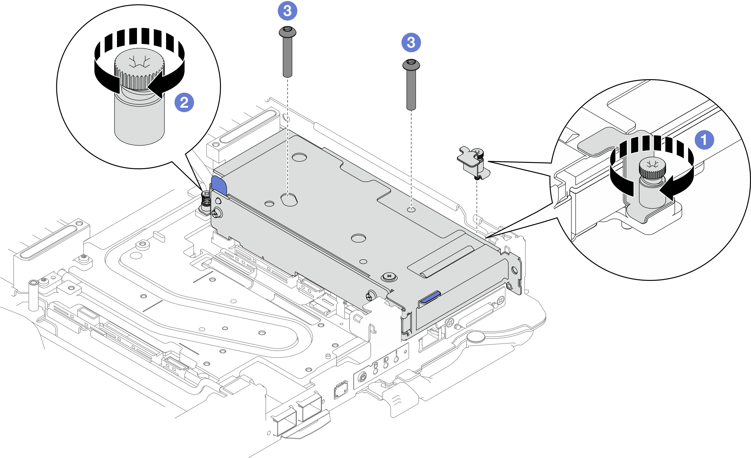
Installieren Sie die Abdeckung des Einbaurahmens. Siehe Abdeckung des Einbaurahmens installieren.
Installieren Sie den Einbaurahmen im Gehäuse. Siehe DWC Einbaurahmen im Gehäuse installieren.
- Schließen Sie alle erforderlichen externen Kabel an der Lösung an.AnmerkungSchließen Sie die QSFP-Kabel an der Lösung an. Dies erfordert zusätzliche Kraft.
Überprüfen Sie die Betriebsanzeige auf jedem Knoten, um sicherzustellen, dass sie von schnellem zum langsamem Blinken wechselt und so darauf hinweist, dass alle Knoten zum Einschalten bereit sind.