PCIe adapter in compute node cable routing
Use this information to route the cables for PCIe adapters in the compute node.
PCIe adapter configuration and cable routing
Shared I/O configuration for ConnectX-6 with the auxiliary adapter kit
Shared I/O configuration requires specific power on and power off sequence for the two nodes, see below:
Power on sequence: first, power on the node with main adapter (right node); then, power on the node with auxiliary adapter (left node).
Power off sequence: first, power off the node with auxiliary adapter (left node); then, power off the node with main adapter (right node).
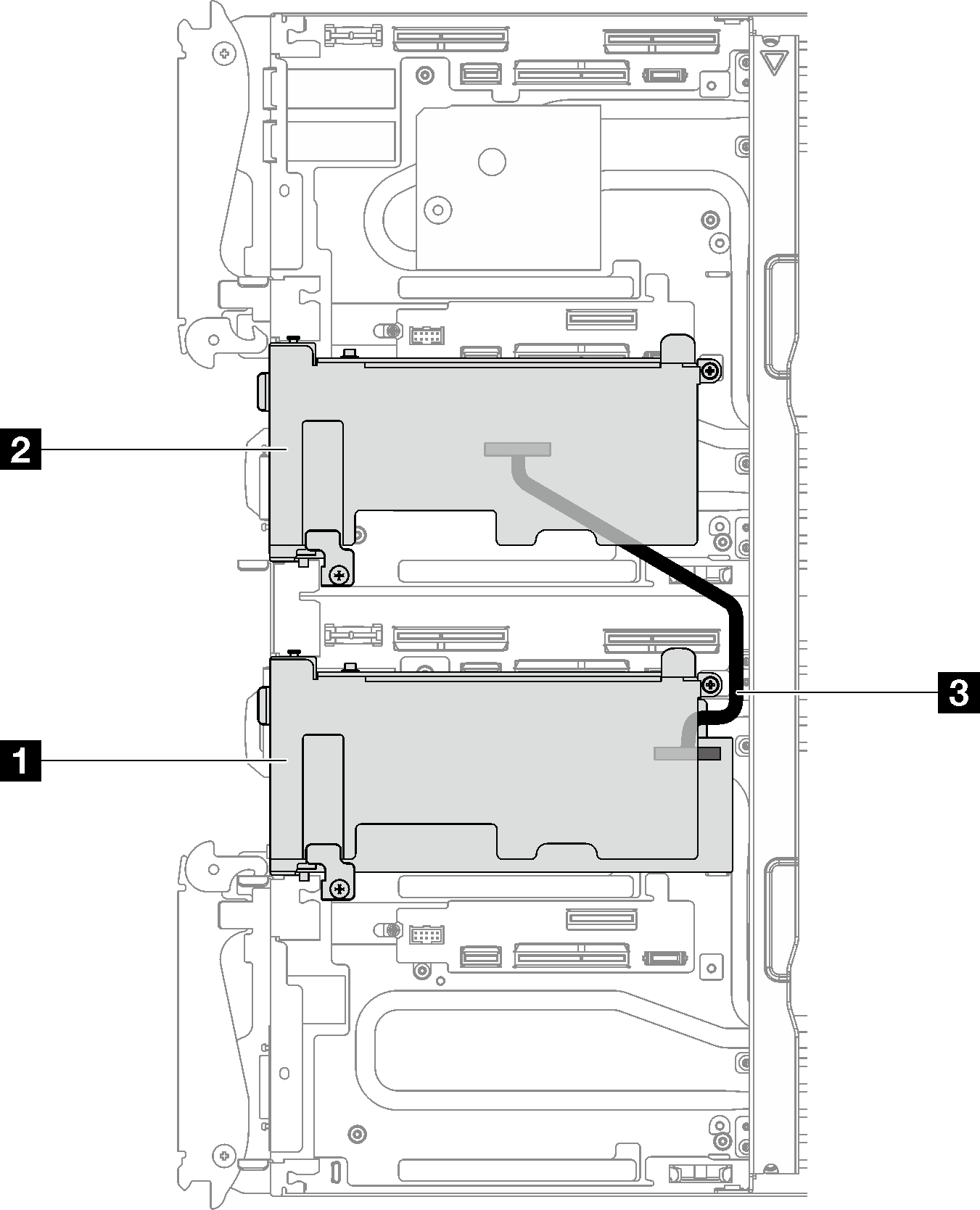
| 1 Main adapter with riser |
| 2 Auxiliary adapter with riser |
| 3 350 mm IPEX cable (CX-6) |
Shared I/O configuration for ConnectX-6 without auxiliary adapter kit, ConnectX-7 NDR 200, and ConnectX-7 NDR 400
ConnectX-6 without the auxiliary adapter kit.
ConnectX-7 NDR 200 and ConnectX-7 NDR 400
Shared I/O configuration requires specific power on and power off sequence for the two nodes, see below:
Power on sequence: first, power on the node with main adapter (right node); then, power on the node with auxiliary adapter (left node).
Power off sequence: first, power off the node with auxiliary adapter (left node); then, power off the node with main adapter (right node).
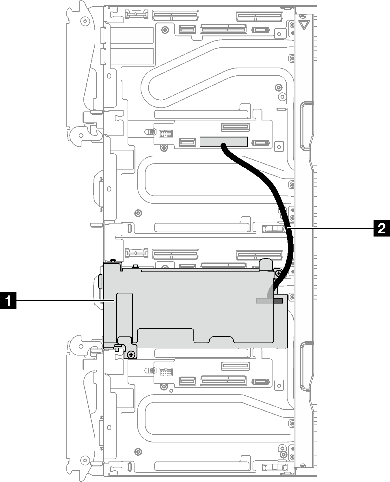
| 1 Main adapter with riser (right node) |
| 2 SD650 V3 Shared I/O cable (190 mm). The cable is directly connected to PCIe riser 1 slot on system board of the left node. |
Socket direct configuration for ConnectX-7 NDR 200/ConnectX-7 NDR 400
This configuration supports ConnectX-7 NDR 200 and ConnectX-7 NDR 400.
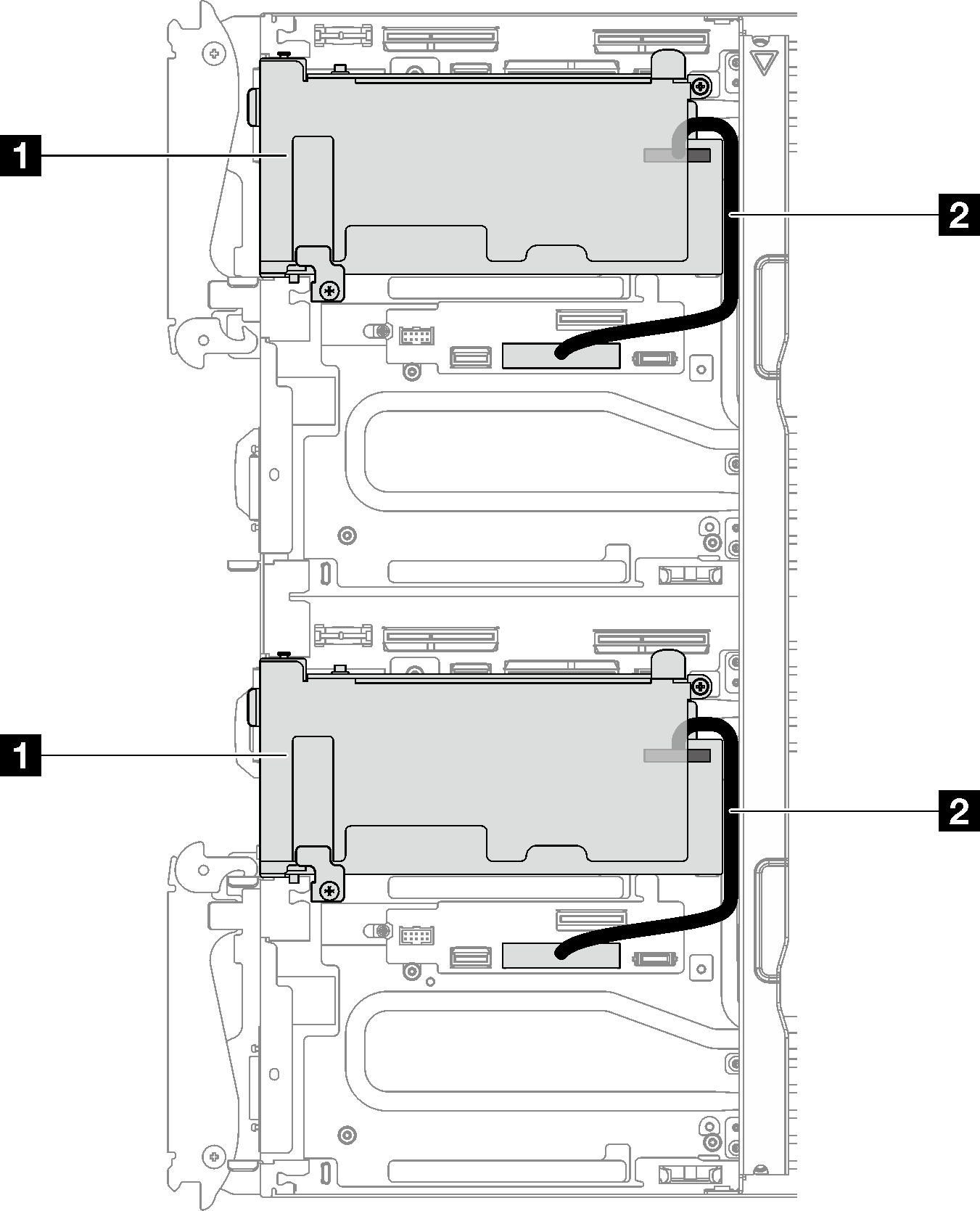
| 1 Main adapter with riser |
| 2 SD650 V3 Share I/O cable (190 mm). The cable is directly connected to PCIe riser 1 slot on the system board of the left node or right node. |