Compute node controls, connectors, and LEDs
Use this information for details about the controls, connectors, and LEDs on the control panel of the compute node.
The following illustration identifies the buttons, connectors, and LEDs on the control panel.
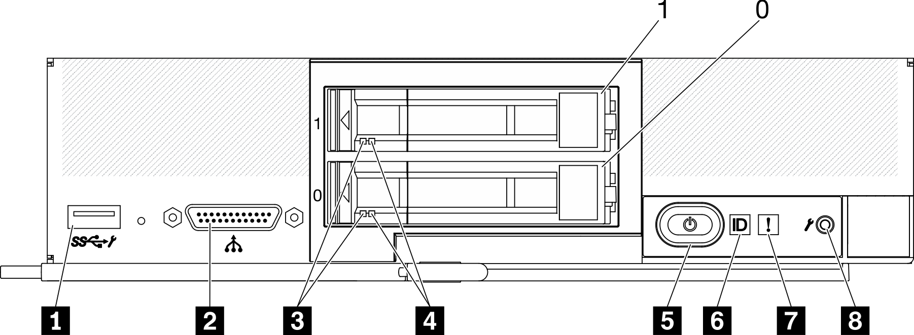
| 1 USB 3.2 Gen 1 connector USB 2.0 only when accessing Lenovo XClarity Controller via a mobile device. | 5 Power button/LED (green) |
| 2 KVM cable connector (console breakout cable) | 6 Identification LED |
| 3 Drive activity LED (green) | 7 Fault LED (yellow) |
| 4 Drive status LED (yellow) | 8 USB management button |
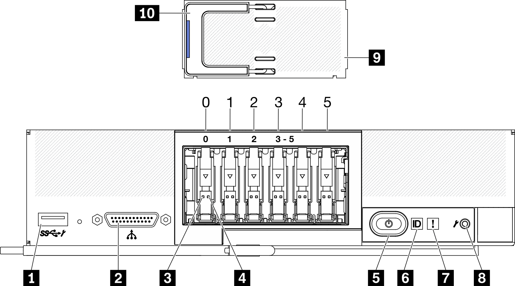
| 1 USB 3.2 Gen 1 connector USB 2.0 only when accessing Lenovo XClarity Controller via a mobile device. | 6 Identification LED |
| 2 KVM cable connector (console breakout cable) | 7 Fault LED (yellow) |
| 3 Drive activity LED (green) | 8 USB management button |
| 4 Drive status LED (yellow) | 9 EDSFF drive bezel |
| 5 Power button/LED (green) | 10 EDSFF drive bezel handle |
- 1 USB 3.2 Gen 1 connector
- Connect a USB device to this USB 3.2 Gen 1 connector.
- 2 KVM cable connector
- Connect the KVM cable to this connector. See KVM cable for more information. The KVM cable may also be referred to as the console breakout cable.AttentionUse only the KVM cable that comes with the chassis. Attempting to connect other KVM cable types might damage the KVM cable and the compute node.NoteIt is best practice to connect the KVM cable to only one compute node at a time in each
Lenovo Flex System Enterprise Chassis. - 3 Drive activity LED (green)
- Green LEDs are on all hot-swap drives. When this green LED is lit, it indicates that there is activity on the associated hard disk drive or solid-state drive.
When this LED is flashing, it indicates that the drive is actively reading or writing data.
For SAS and SATA drives, this LED is off when the drive is powered but not active.
For NVMe (PCIe) SSDs and EDSFF, this LED is on solid when the drive is powered but not active.
NoteThe drive activity LED might be in a different location on the front of the drive, depending on the drive type that is installed. - 4 Drive status LED (yellow)
- The state of this yellow LED indicates an error condition or the RAID status of the associated hard disk drive or solid-state drive:
- When the yellow LED is lit, it means an error has occurred with the associated drive. The LED turns off only after the error is corrected. You can check the CMM event log to determine the source of the condition.
- When the yellow LED flashes slowly, it indicates that the associated drive is being rebuilt.
- When the yellow LED flashes rapidly, it indicates that the associated drive is being located.
NoteThe hard disk drive status LED might be in a different location on the front of the hard disk drive, depending on the drive type that is installed. - 5 Power button/LED (green)
- When the compute node is connected to power through the Lenovo Flex System Enterprise Chassis, press this button to turn on or turn off the compute node.NoteThe power button works only if local power control is enabled for the compute node. Local power control is enabled and disabled through the CMM
power command and the CMM web interface. - For more information about the CMM power command, see the Flex System Chassis Management Module: Command-Line Interface Reference Guide.
- From the CMM web interface, select Compute Nodes from the Chassis Management menu. For more information, see the Flex System Chassis Management Module: User's Guide at "Flex System Chassis Management Module: User's Guide". All fields and options are described in the CMM web interface online help.
After the compute node is removed from the chassis, press and hold this button to activate the system-board LEDs (Light Path Diagnostics panel). See Viewing the Light Path Diagnostics LEDs for more information.
This button is also the power LED. This green LED indicates the power status of the compute node:- Flashing rapidly (Four times per second): The LED flashes rapidly for one of the following reasons:
- The compute node has been installed in a powered chassis. When you install the compute node, the LED flashes rapidly while the XClarity Controller in the compute node is initializing and synchronizing with the Chassis Management Module. The time required for a compute node to initialize varies by system configuration.
- Power permissions have not been assigned to the compute node through the Chassis Management Module.
- The Lenovo Flex System Enterprise Chassis does not have enough power to turn on the compute node.
- The Lenovo XClarity Controller in the compute node is not communicating with the Chassis Management Module.
The power LED blink rate slows when the compute node is ready to be turned on.
- Flashing slowly (One time per second): The compute node is connected to power through the Lenovo Flex System Enterprise Chassis and is ready to be turned on.
- Lit continuously: The compute node is connected to power through the Lenovo Flex System Enterprise Chassis and is turned on.
When the compute node is on, pressing this button causes an orderly shutdown of the compute node so that it can be removed safely from the chassis. This includes shutting down the operating system (if possible) and removing power from the compute node.
AttentionIf an operating system is running, you might have to press the button for approximately 4 seconds to initiate the shutdown. This forces the operating system to shut down immediately. Data loss is possible. - 6 Identification LED (blue)
- The system administrator can remotely light this blue LED to aid in visually locating the compute node. When this LED is lit, the identification LED on the Lenovo Flex System Enterprise Chassis is also lit. The identification LED can be lit and turned off through the CMM led command, the CMM web interface and the Lenovo XClarity Administrator application (if installed).
There are four states of identification LED:
Table 3. Identification LED state LED state Description Operation required for this state Off When the USB connector is not in shared mode, this is the default state and no operation required.
When the USB connector is in shared mode, this indicates that the USB connector is available to be switched to Lenovo XClarity Controller management mode, where you can access the Lenovo XClarity Controller directly via a mobile device connected to the USB connector of the compute node.
When the USB connector is not in shared mode, no operation required.
When the USB connector is in shared mode, to switch the USB connector to Lenovo XClarity Controller management mode, do the following:
Press the USB management button for three seconds, or
Use the Lenovo XClarity Controller
Solid On Compute node is in locally manual operation status.
When the USB connector is not in shared mode, use CMM or Lenovo XClarity Controller to return the ID LED to Off state.
When the USB connector is in shared mode, to switch the USB connector to Lenovo XClarity Controller management mode, do the following:
Press the USB management button for three seconds, or
Use the Lenovo XClarity Controller
Blinking (blink one time per second) Slow blinking (blink one time every two seconds) Compute node is power on. The USB connector is in shared mode and in Lenovo XClarity Controller management mode, where you can access the Lenovo XClarity Controller directly via a mobile device connected to the USB connector of the compute node.
ID LED state change is not available in the state.
To Switch the USB port to default mode, do the following:
Press USB management button for three seconds, or
Use the Lenovo XClarity Controller
- For more information about the CMM led command, see Flex System Chassis Management Module: Command-Line Interface Reference Guide.
- From the CMM web interface, select Compute Nodes from the Chassis Management menu. For more information, see "Flex System Chassis Management Module: User's Guide". All fields and options are described in the CMM web interface online help.
- For more information about the Lenovo XClarity Administrator application, see the Lenovo XClarity Administrator information page.
- 7 Fault LED (yellow)
- When this yellow LED is lit, it indicates that a system error has occurred in the compute node. In addition, the fault LED on the chassis system LED panel is lit. You can check the CMM event log and the Light Path Diagnostics LEDs to determine the source of the condition. See Light Path Diagnostics for more information about the LEDs on the compute node.The fault LED turns off only after the error is corrected.NoteWhen the fault LED turns off, you should also clear the Lenovo XClarity Controller event log. Use the Setup utility to clear the Lenovo XClarity Controller event log.
- 8 USB management button
- Access this button by using a small pointed device.
- 9 EDSFF drive bezel
- The six EDSFF drive compute node should always operate with the EDSFF drive bezel installed.NoteThe EDSFF drive bezel is present only for compute node with EDSFF drives.
- 10 EDSFF drive bezel handle
- Use this handle to assist EDSFF drive bezel removal and installation.NoteThe blue strip on the handle must be on the left side when the EDSFF drive bezel is installed on the EDSFF drive cage.