Viewing the Light Path Diagnostics LEDs
Use this information to locate and identify the Light Path Diagnostics LEDs.
Before you work inside the compute node to view the Light Path Diagnostics LEDs, read the safety information, which is available at Safety inspection checklist and Installation Guidelines.
If an error occurs, view the Light Path Diagnostics LEDs in the following order:
- Look at the control panel on the front of the compute node.Figure 1. Two 2.5-inch drives compute node control panel buttons, connectors, and LEDs
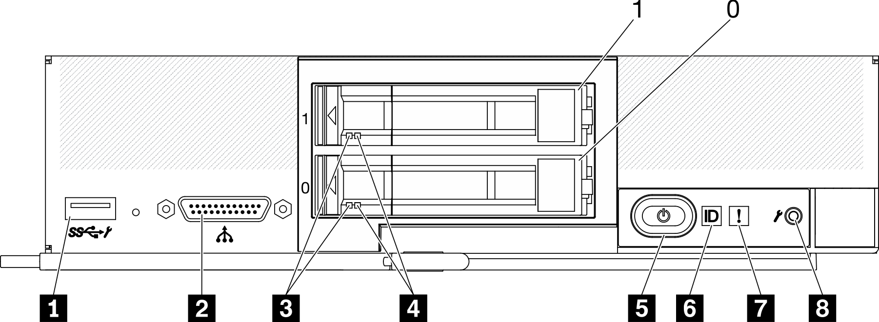 Figure 2. Six ESDFF drives compute node control panel buttons, connectors, and LEDs
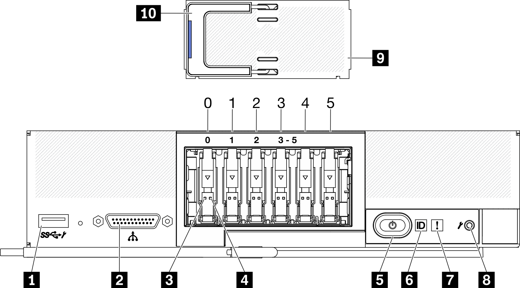
Table 1. Compute node control panel buttons, connectors, and LEDs 1 USB 3.2 Gen 1 connector USB 2.0 only when accessing Lenovo XClarity Controller via a mobile device.
6 Identification LED 2 KVM connector 7 Fault LED (yellow) 3 Drive activity LED (green) 8 USB management button 4 Drive status LED (yellow) 9 EDSFF drive bezel (Six ESDFF drives compute node only) 5 Power button/LED (green) 10 EDSFF drive bezel handle (Six ESDFF drives compute node only) - If the fault LED is lit, it indicates that an error has occurred; view the light path diagnostics panel and LEDs to isolate the failing component.
- To view the light path diagnostics panel LEDs, select one of the following procedures:
- You can view the LEDs through the CMM led command, the CMM web interface and the Lenovo XClarity Administrator application (if installed).
- For more information about the CMM led command, see Flex System Chassis Management Module: Command-Line Interface Reference Guide at Flex System Chassis Management Module: Command-Line Interface Reference Guide.
- From the CMM web interface, select Compute Nodes from the Chassis Management menu. For more information, see the Flex System Chassis Management Module: User's Guide at "Flex System Chassis Management Module: User's Guide". All fields and options are described in the CMM web interface online help.
- For more information about the Lenovo XClarity Administrator application, see the Lenovo XClarity Administrator information page.
- If you are in the same location as the compute node, you can complete the following steps:
Remove the compute node from the Lenovo Flex System Enterprise Chassis. See Remove the compute node from chassis.
Carefully lay the compute node on a flat, static-protective surface.
Open the compute node cover. See Remove the compute node cover.
Locate the Light Path Diagnostics panel.
Figure 3. Light Path Diagnostics panel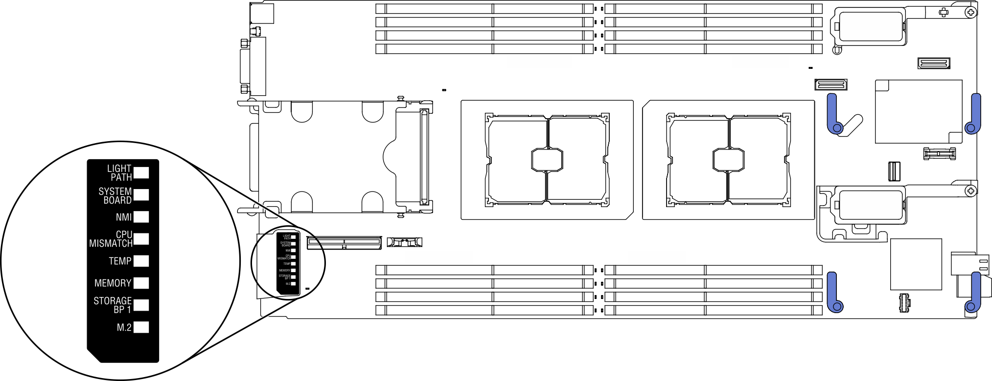
Press and hold the power button on the control panel on the front of the compute node. When you press the power button, LEDs on the light path diagnostics panel and the system board will be lit if there are any hardware-related issues.
NoteThe power source for Light Path Diagnostics panel is designed only to last a short time.Identify the errors indicated by the Light Path Diagnostics panel LEDs. See Light Path Diagnostics panel LEDs.
- You can view the LEDs through the CMM led command, the CMM web interface and the Lenovo XClarity Administrator application (if installed).