ThinkSystem SR665 (7D2V, 7D2W)
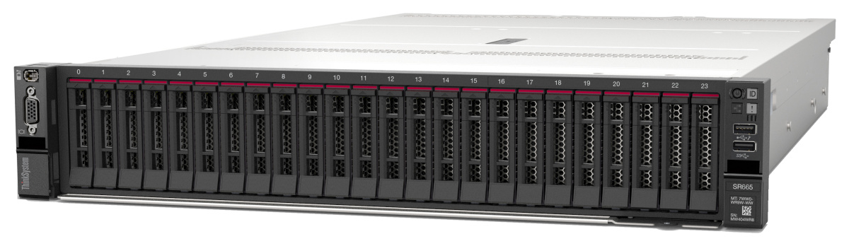
The ThinkSystem SR665 server (machine type: 7D2V, 7D2W) is a 2-socket 2U server that features the new AMD® EPYCTM family of processors. The server offers a broad selection of drive and slot configurations and offers high performance and expansion for various IT workloads. Combining performance and flexibility, the server is a great choice for enterprises of all sizes.
Give documentation feedback