Kabelführung für Konfiguration F
In diesem Abschnitt erfahren Sie, wie die Kabelführung für Konfiguration F funktioniert.
Die Kabelführung für Konfiguration F umfasst folgende Komponenten:
Kabelführung der Rückwandplatine für Laufwerke
Kabelführung für E/A-Erweiterungsplatinenmodul an der Vorderseite
Kabelführung für Retimer-Baugruppe
Kabelführung für Kühlplattenbaugruppe
Die Kabelführung für diese Komponenten wird unten dargestellt.
Kabelführung der Rückwandplatine für Laufwerke
Schließen Sie die Signalkabel und Netzkabel der Rückwandplatine für Laufwerke wie dargestellt an.
Abbildung 1. Kabelführung der Rückwandplatine für Laufwerke – Konfiguration F
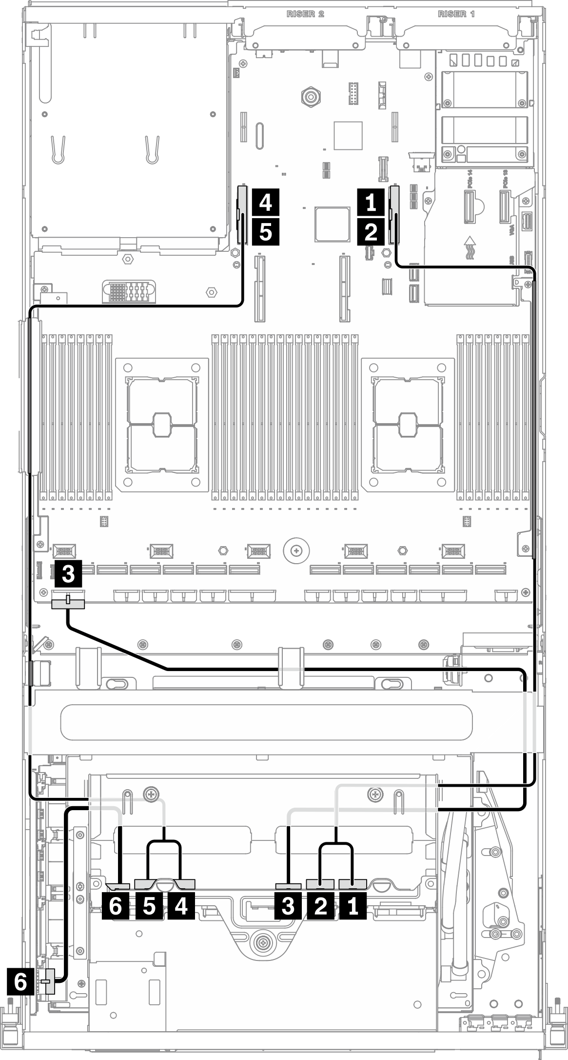
| Vom | Zu | ||
|---|---|---|---|
| Rückwandplatine für Laufwerk (rechte Seite) | 1 NVMe 2‑3 | Systemplatine | 1 PCIe-Anschluss 16 |
| 2 NVMe 0‑1 | 2 PCIe-Anschluss 16 | ||
| 3 Netzteilanschluss | 3 Netzteilanschluss für Rückwandplatine 1 | ||
| Rückwandplatine für Laufwerk (linke Seite) | 4 NVMe 2‑3 | 4 PCIe-Anschluss 15 | |
| 5 NVMe 0‑1 | 5 PCIe-Anschluss 15 | ||
| 6 Netzteilanschluss | Retimer-Baugruppe | 6 Netzteilanschluss für Rückwandplatine | |
Kabelführung für E/A-Erweiterungsplatinenmodul an der Vorderseite
Schließen Sie die Signalkabel und das Netzkabel der E/A-Erweiterungsplatine an der Vorderseite wie dargestellt an.
Abbildung 2. Kabelführung für E/A-Erweiterungsplatinenmodul an der Vorderseite – Konfiguration F
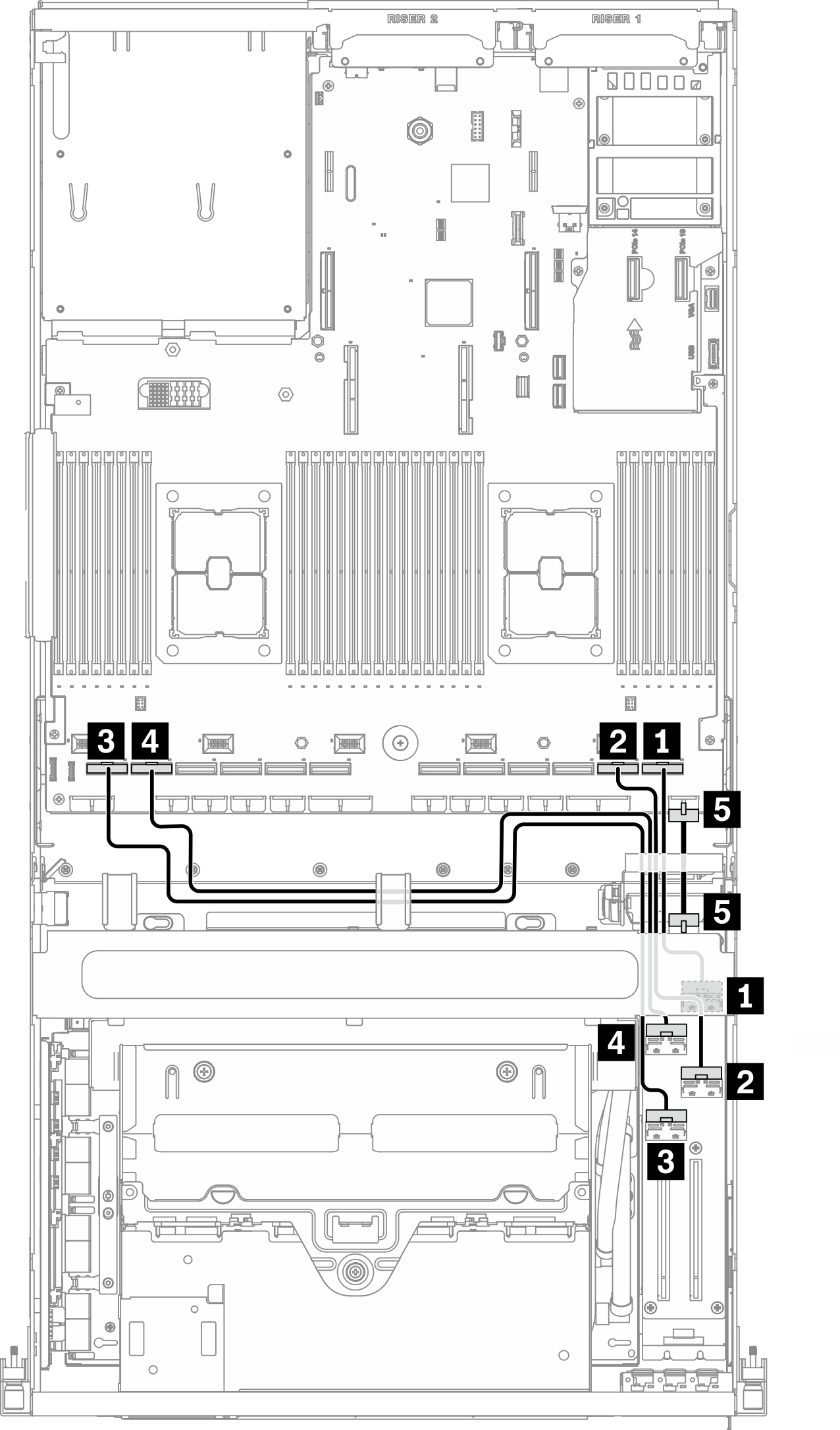
| Vom | Zu | |||
|---|---|---|---|---|
| E/A-Erweiterungsplatine an der Vorderseite | 1 MCIO-Anschluss B | Steckplatz 1 | Systemplatine | 1 PCIe-Anschluss 1 |
| 2 MCIO-Anschluss A | 2 PCIe-Anschluss 2 | |||
| 3 MCIO-Anschluss C | Steckplatz 2 | 3 PCIe-Anschluss 12 | ||
| 4 MCIO-Anschluss D | 4 PCIe-Anschluss 11 | |||
| 5 Netzteilanschluss | 5 Netzteilanschluss für E/A-Erweiterungsplatine an der Vorderseite | |||
Kabelführung für Retimer-Baugruppe
Die Kabelführung für die Retimer-Baugruppe umfasst folgende Komponenten:
Netzkabel der Retimer-Baugruppe
Signalkabel der Retimer-Baugruppe
Netzkabel der Retimer-Baugruppe
Schließen Sie das Netzkabel der Retimer-Baugruppe wie dargestellt an.
Abbildung 3. Kabelführung für Retimer-Baugruppe (Netzkabel) – Konfiguration F
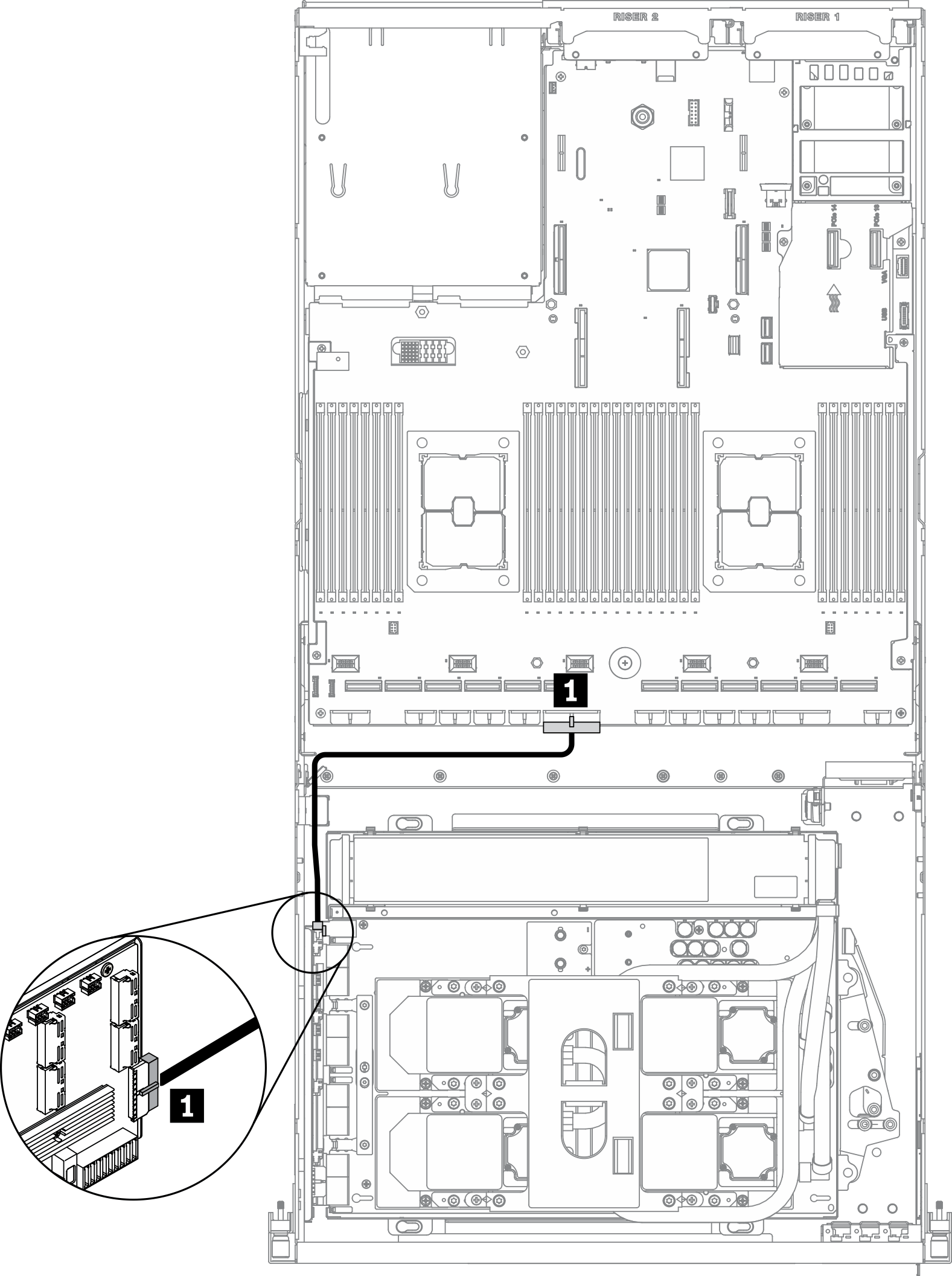
| Vom | Zu | ||
|---|---|---|---|
| Retimer-Baugruppe | 1 Netzteilanschluss | Systemplatine | 1 Anschluss 2 für PCIe-Adapter für Stromversorgungsplatine |
Signalkabel der Retimer-Baugruppe
Schließen Sie die Signalkabel der Retimer-Baugruppe wie dargestellt an.
Abbildung 4. Kabelführung für Retimer-Baugruppe (Signalkabel) – Konfiguration F
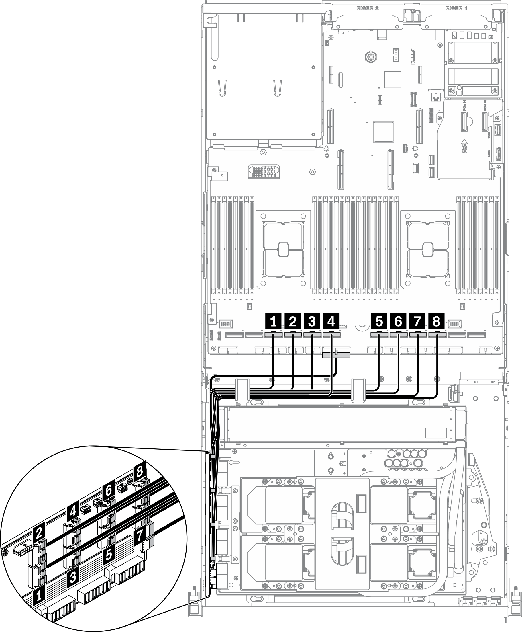
| Vom | Zu | ||
|---|---|---|---|
| Retimer-Baugruppe | 1 MCIO-Anschluss A | Systemplatine | 1 PCIe-Anschluss 10 |
| 2 MCIO-Anschluss B | 2 PCIe-Anschluss 9 | ||
| 3 MCIO-Anschluss C | 3 PCIe-Anschluss 8 | ||
| 4 MCIO-Anschluss D | 4 PCIe-Anschluss 7 | ||
| 5 MCIO-Anschluss E | 5 PCIe-Anschluss 6 | ||
| 6 MCIO-Anschluss F | 6 PCIe-Anschluss 5 | ||
| 7 MCIO-Anschluss G | 7 PCIe-Anschluss 4 | ||
| 8 MCIO-Anschluss H | 8 PCIe-Anschluss 3 | ||
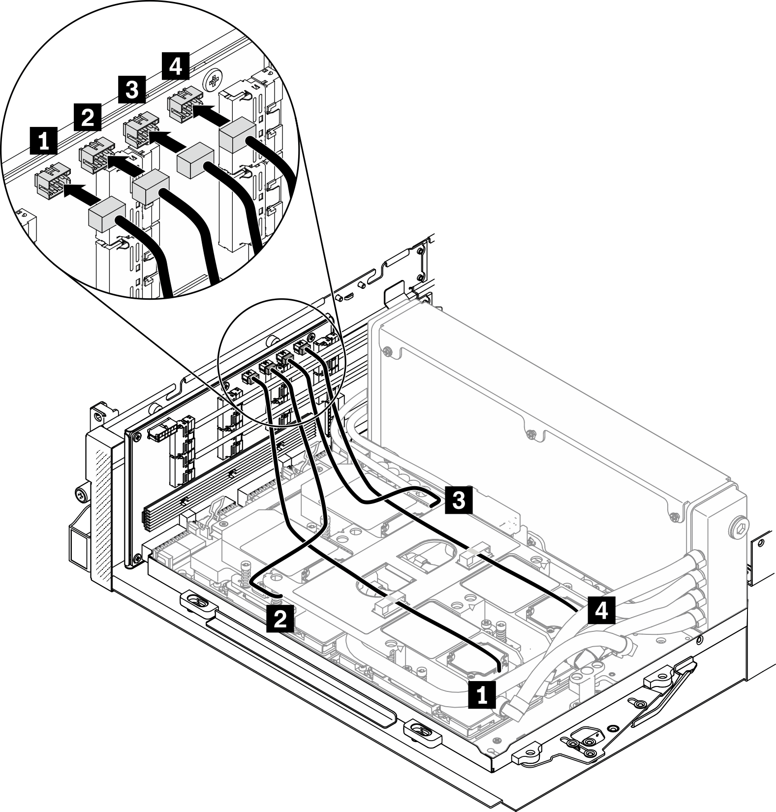
Kabelführung für Kühlplattenbaugruppe
Schließen Sie die Pumpenkabel der Kühlplattenbaugruppe wie dargestellt an die Retimer-Baugruppe an.
Abbildung 5. Kabelführung für Pumpenkabel der Kühlplattenbaugruppe zur Retimer-Baugruppe – Konfiguration F
| Vom | Zu | ||
|---|---|---|---|
| Retimer-Baugruppe | 1 Pumpenkabelanschluss 1 für Kühlplattenbaugruppe | Kühlplattenbaugruppe | 1 Kühlplatte 1 |
| 2 Pumpenkabelanschluss 2 für Kühlplattenbaugruppe | 2 Kühlplatte 2 | ||
| 3 Pumpenkabelanschluss 3 für Kühlplattenbaugruppe | 3 Kühlplatte 3 | ||
| 4 Pumpenkabelanschluss 4 für Kühlplattenbaugruppe | 4 Kühlplatte 4 | ||
Feedback geben