Configuration F cable routing
Follow the instructions in this section to learn how to do cable routing for Configuration F.
Configuration F cable routing includes the following components:
Drive backplane cable routing
Front I/O expansion board cable routing
Retimer assembly cable routing
Cold plate assembly cable routing
Cabling for these components are illustrated below.
Drive backplane cable routing
Connect the drive backplane signal cables and power cables as illustrated.
Figure 1. Drive backplane cable routing – Configuration F
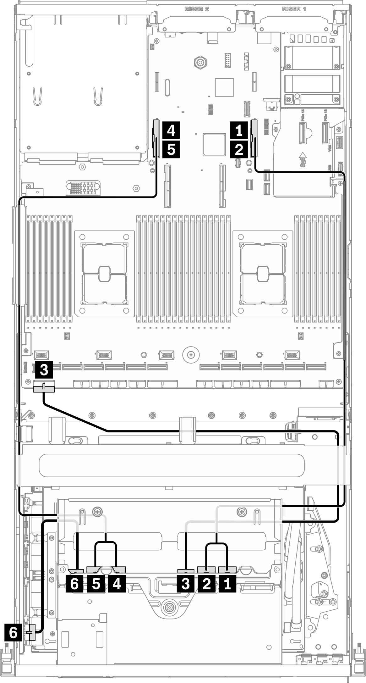
| From | To | ||
|---|---|---|---|
| Drive backplane (right side) | 1 NVMe 2-3 | System board | 1 PCIe connector 16 |
| 2 NVMe 0-1 | 2 PCIe connector 16 | ||
| 3 Power connector | 3 Backplane power 1 connector | ||
| Drive backplane (left side) | 4 NVMe 2-3 | 4 PCIe connector 15 | |
| 5 NVMe 0-1 | 5 PCIe connector 15 | ||
| 6 Power connector | Retimer assembly | 6 Backplane power connector | |
Front I/O expansion board cable routing
Connect the front I/O expansion board signal cables and power cable as illustrated.
Figure 2. Front I/O expansion board cable routing – Configuration F
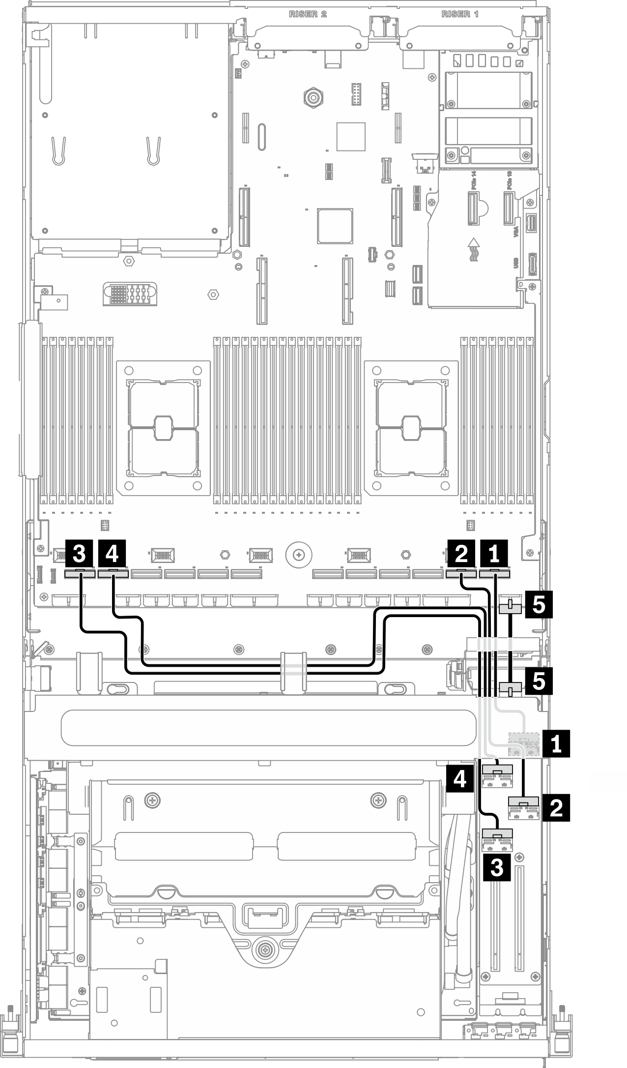
| From | To | |||
|---|---|---|---|---|
| Front I/O expansion board | 1 MCIO connector B | Slot #1 | System board | 1 PCIe connector 1 |
| 2 MCIO connector A | 2 PCIe connector 2 | |||
| 3 MCIO connector C | Slot #2 | 3 PCIe connector 12 | ||
| 4 MCIO connector D | 4 PCIe connector 11 | |||
| 5 Power connector | 5 Front I/O expansion board power connector | |||
Retimer assembly cable routing
Retimer assembly cable routing includes the following items:
Retimer assembly power cable
Retimer assembly signal cables
Retimer assembly power cable
Connect the retimer assembly power cable as illustrated.
Figure 3. Retimer assembly cable routing (power cable) – Configuration F
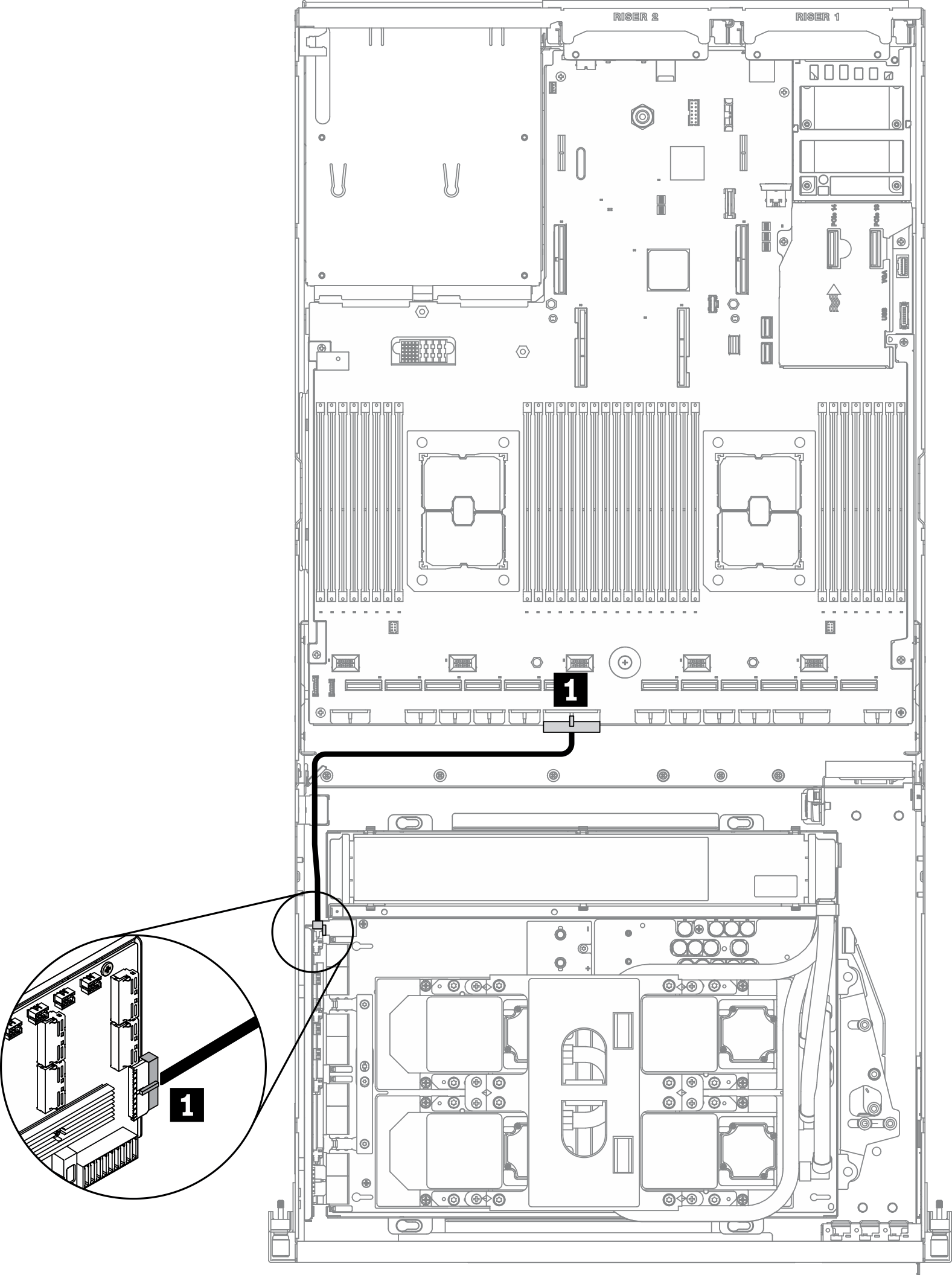
| From | To | ||
|---|---|---|---|
| Retimer assembly | 1 Power connector | System board | 1 PCIe adapter distribution board power 2 connector |
Retimer assembly signal cables
Connect the retimer assembly signal cables as illustrated.
Figure 4. Retimer assembly cable routing (signal cables) – Configuration F
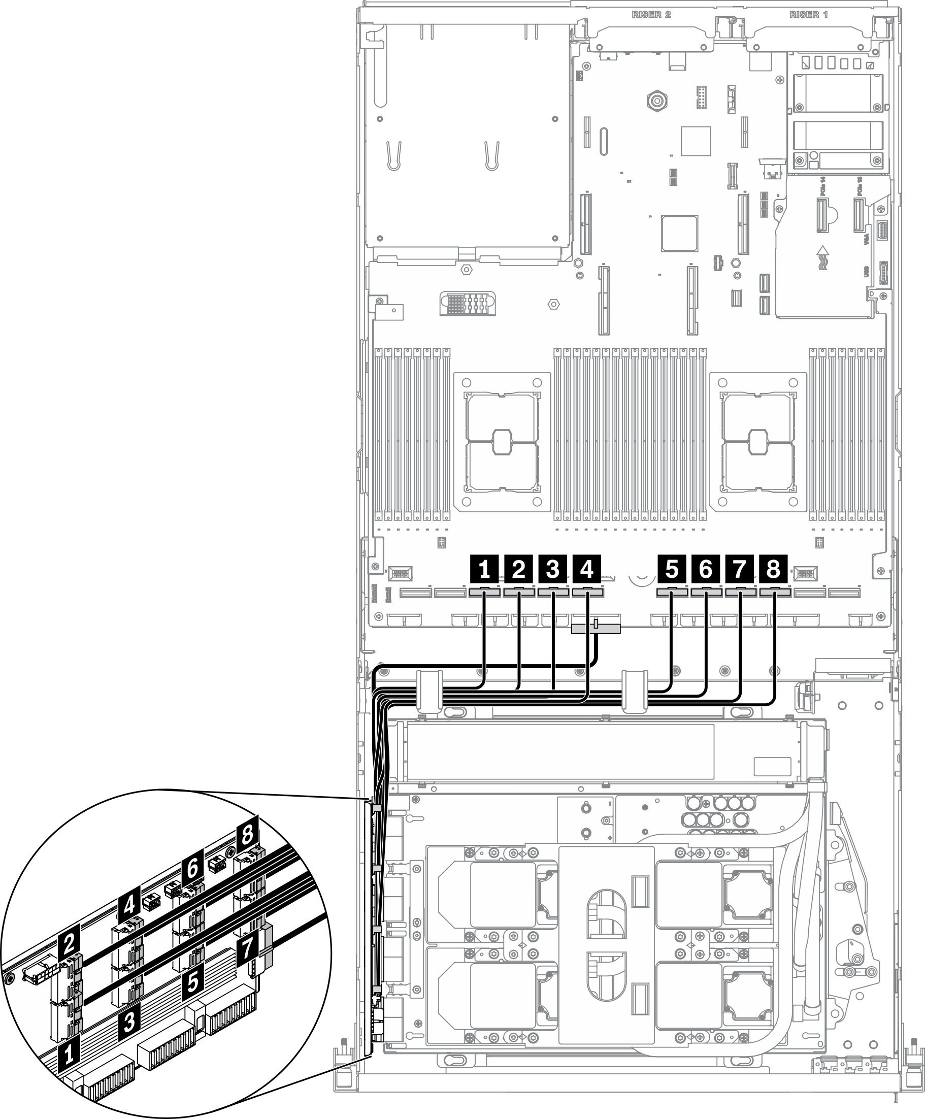
| From | To | ||
|---|---|---|---|
| Retimer assembly | 1 MCIO connector A | System board | 1 PCIe connector 10 |
| 2 MCIO connector B | 2 PCIe connector 9 | ||
| 3 MCIO connector C | 3 PCIe connector 8 | ||
| 4 MCIO connector D | 4 PCIe connector 7 | ||
| 5 MCIO connector E | 5 PCIe connector 6 | ||
| 6 MCIO connector F | 6 PCIe connector 5 | ||
| 7 MCIO connector G | 7 PCIe connector 4 | ||
| 8 MCIO connector H | 8 PCIe connector 3 | ||
Cold plate assembly cable routing
Connect the cold plate assembly pump cables to the retimer assembly as illustrated.
Figure 5. Cold plate assembly pump cables to the retimer assembly cable routing – Configuration F
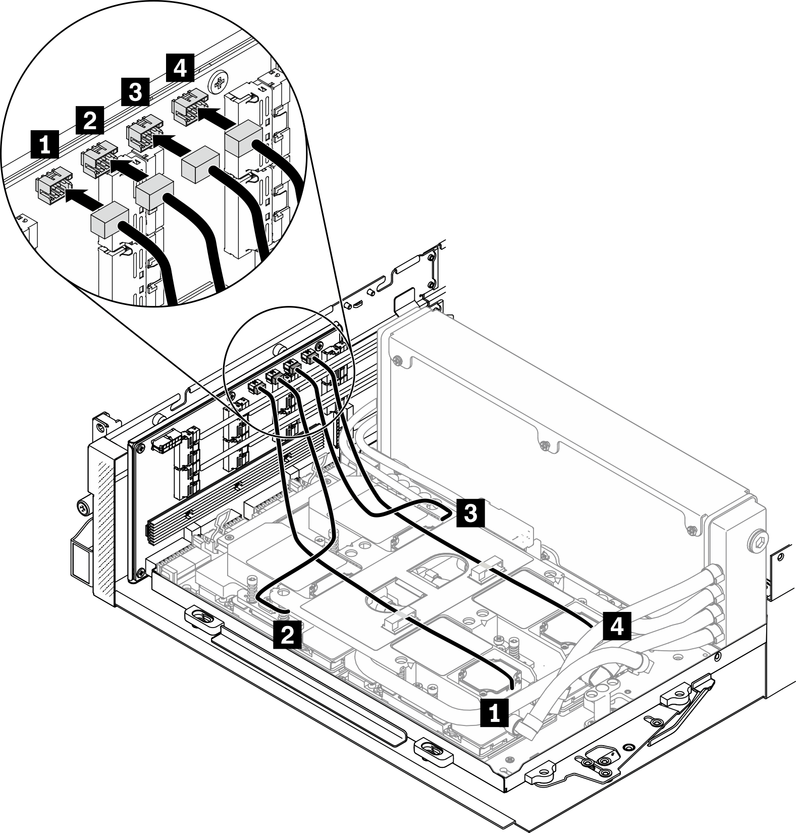
| From | To | ||
|---|---|---|---|
| Retimer assembly | 1 Cold plate assembly pump cable connector 1 | Cold plate assembly | 1 Cold plate 1 |
| 2 Cold plate assembly pump cable connector 2 | 2 Cold plate 2 | ||
| 3 Cold plate assembly pump cable connector 3 | 3 Cold plate 3 | ||
| 4 Cold plate assembly pump cable connector 4 | 4 Cold plate 4 | ||
Give documentation feedback