4-DW GPU Model with 8x 2.5-inch drives cable routing
Follow the instructions in this section to learn how to do cable routing for 4-DW GPU Model with 8x 2.5-inch drives.
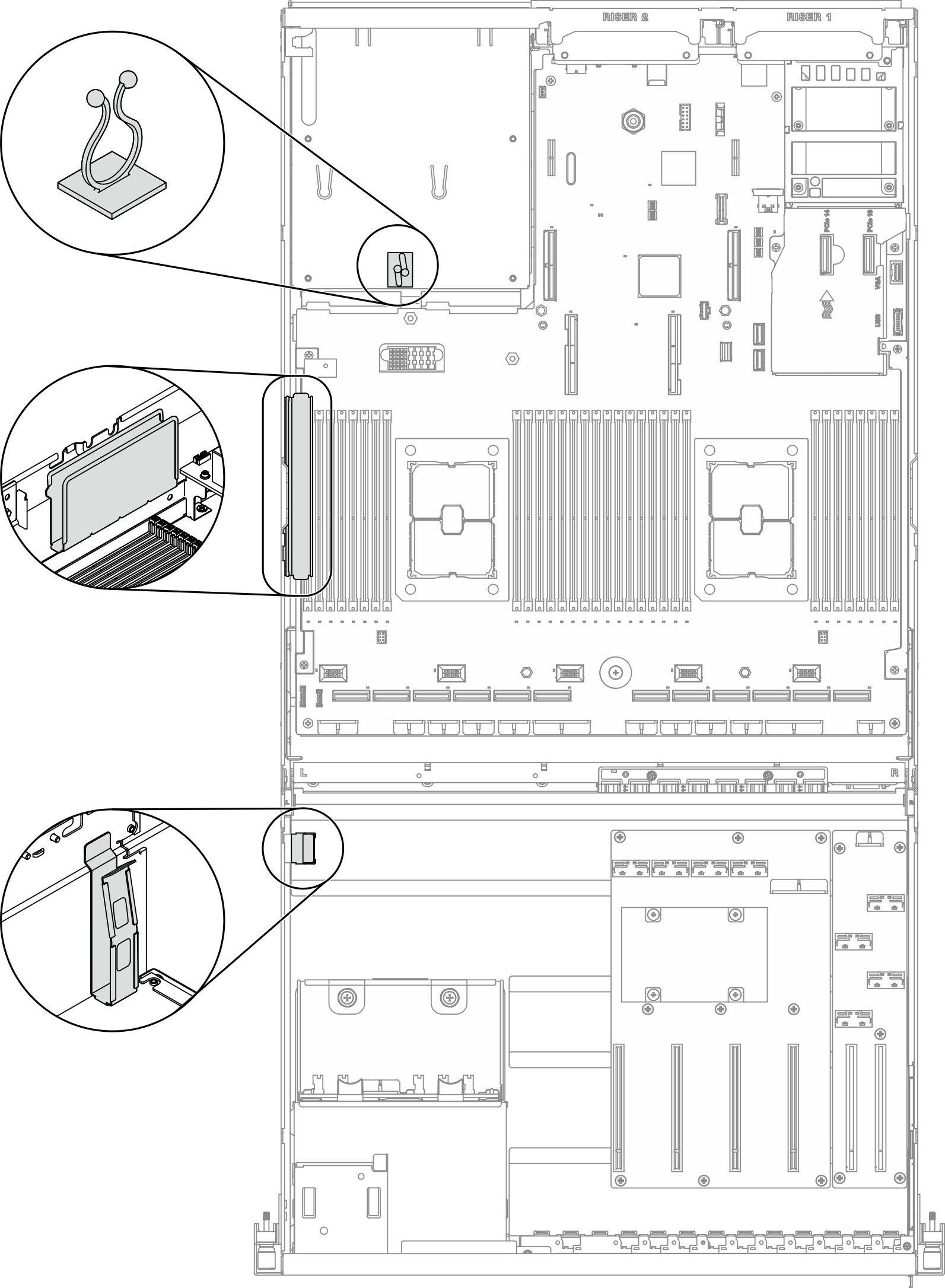
Identifying connectors
For the connectors on system board, see System-board connectors.
For the connectors on the drive backplane, GPU distribution board, rear riser, and front I/O expansion board, see Identifying connectors.
4-DW GPU Model with 8x 2.5-inch drives configurations
Cable routing is different by configuration. See the table below for the configuration that matches your server, and refer to the corresponding cable routing guide.
| GPU distribution board | Rear riser 1 | Rear riser 2 | Rear riser 2 installed with HBA/RAID adapter | OCP slot enabled | Front I/O expansion board | Configurations |
|---|---|---|---|---|---|---|
| Four PCIe x16 slot PCIe distribution board | V | V | Configuration A | |||
| V | V | V | Configuration A with HBA/RAID adapter | |||
| V | V | Configuration A with HBA/RAID adapter | ||||
| V | Configuration C | |||||
| Four PCIe x16 slot switched PCIe distribution board | V | V | V | Configuration H | ||
| V | V | V | Configuration H with HBA/RAID adapter | |||
| V | V | Configuration H with HBA/RAID adapter | ||||
| V | V | Configuration I |
For Configuration A, see Configuration A cable routing
For Configuration A with HBA/RAID adapter, see Configuration A with HBA/RAID adapter cable routing
For Configuration C, see Configuration C cable routing
For Configuration H, see Configuration H cable routing
For Configuration H with HBA/RAID adapter, see Configuration H with HBA/RAID adapter cable routing
For Configuration I, see Configuration I cable routing