Configuration H with HBA/RAID adapter cable routing
Follow the instructions in this section to learn how to do cable routing for Configuration H with HBA/RAID adapter.
Configuration H with HBA/RAID adapter cable routing includes the following items:
Drive backplane cable routing
GPU distribution board cable routing
Rear riser 1, rear riser 2, and HBA/RAID adapter cable routing
OCP Ethernet adapter cable routing
Cabling for these components are illustrated below.
Drive backplane cable routing
Connect the drive backplane signal cables and power cable as illustrated.
Figure 1. Drive backplane cable routing – Configuration H with HBA/RAID adapter
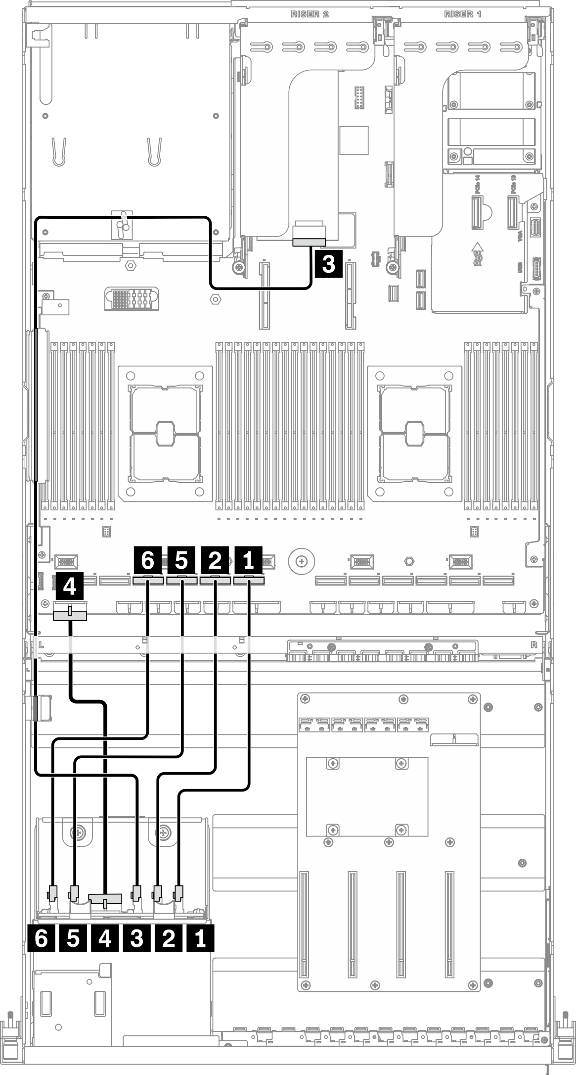
| From | To | ||
|---|---|---|---|
| Drive backplane | 1 NVMe 6-7 | System board | 1 PCIe connector 7 |
| 2 NVMe 4-5 | 2 PCIe connector 8 | ||
| 3 SAS | 3 HBA/RAID adapter installed on rear riser 2 | ||
| 4 Power connector | 4 Backplane power 1 connector | ||
| 5 NVMe 2-3 | 5 PCIe connector 9 | ||
| 6 NVMe 0-1 | 6 PCIe connector 10 | ||
GPU distribution board cable routing
Connect the GPU distribution board signal cables and power cable as illustrated.
Figure 2. GPU distribution board cable routing – Configuration H with HBA/RAID adapter
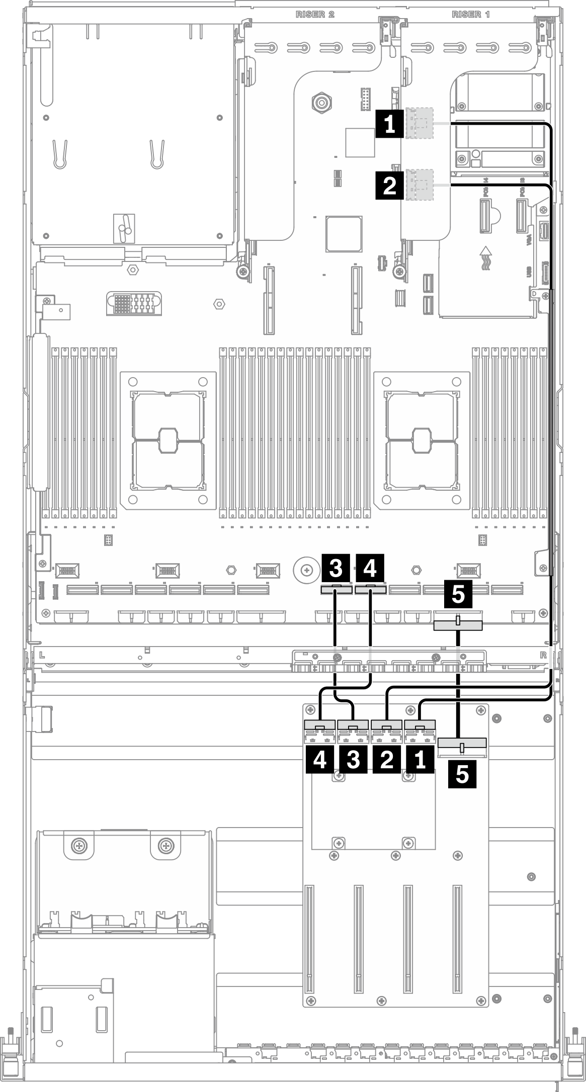
| From | To | |||
|---|---|---|---|---|
| GPU distribution board | 1 MCIO connector A | GPU #3 | Rear riser 1 | 1 MCIO connector A |
| 2 MCIO connector B | GPU #4 | 2 MCIO connector B | ||
| 3 MCIO connector C | GPU #5 | System board | 3 PCIe connector 6 | |
| 4 MCIO connector D | GPU #6 | 4 PCIe connector 5 | ||
| 5 Power connector | 5 PCIe adapter distribution board power 1 connector | |||
Rear riser(s) and HBA/RAID adapter cable routing
Connect the rear riser(s) HBA/RAID adapter signal cables as illustrated.
Figure 3. Rear riser(s) and HBA/RAID adapter cable routing – Configuration H with HBA/RAID adapter
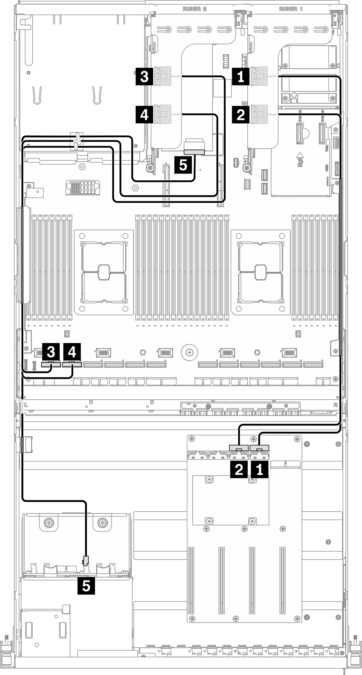
Note: Depending on the configuration, there may be no rear riser 1 in the system.
| From | To | ||
|---|---|---|---|
| Rear riser 1 | 1 MCIO connector A | GPU distribution board | 1 MCIO connector A |
| 2 MCIO connector B | 2 MCIO connector B | ||
| Rear riser 2 | 3 MCIO connector A | System board | 3 PCIe connector 12 |
| 4 MCIO connector B | 4 PCIe connector 11 | ||
| 5 HBA/RAID adapter installed on rear riser 2 | Drive backplane | 5 SAS | |
OCP Ethernet adapter cable routing
Connect the OCP Ethernet adapter signal cable as illustrated.
Figure 4. OCP Ethernet adapter cable routing – Configuration H with HBA/RAID adapter
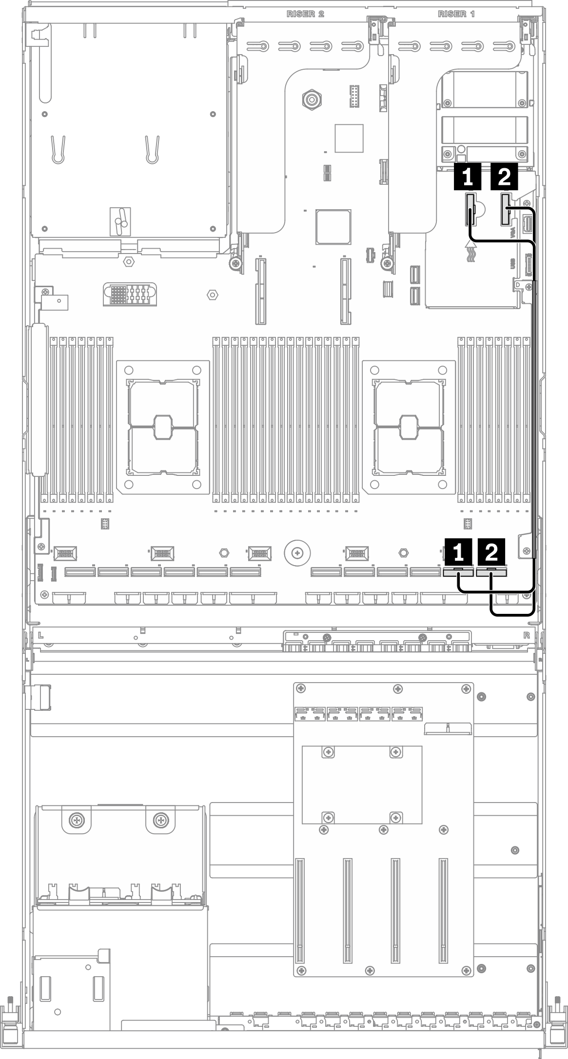
| From | To | ||
|---|---|---|---|
| System board | 1 PCIe connector 14 | System board | 1 PCIe connector 2 |
| 2 PCIe connector 13 | 2 PCIe connector 1 | ||
Give documentation feedback