Vorderes B200 GPU-Kühlplattenmodul entfernen
Führen Sie die Anweisungen in diesem Abschnitt aus, um das vordere B200 GPU-Kühlplattenmodul zu entfernen. Der Vorgang muss von einem qualifizierten Kundendiensttechniker ausgeführt werden.
Zu dieser Aufgabe
- Lesen Sie Installationsrichtlinien und Sicherheitsprüfungscheckliste, um sicherzustellen, dass Sie sicher arbeiten.
- Schalten Sie den Server und die Peripheriegeräte aus und trennen Sie alle Netzkabel und externen Kabel. Siehe Server ausschalten.
- Wenn der Server in einem Rack installiert ist, schieben Sie ihn aus den Laufschienen des Racks heraus, um Zugriff zur oberen Abdeckung zu erhalten oder das Gehäuse aus dem Rack zu schieben. Siehe Server aus dem Rack entfernen.
- Für dieses Verfahren sind zwei Personen und eine Hebevorrichtung vor Ort erforderlich, die bis zu 181kg (400lb) unterstützt. Wenn Ihnen noch keine Hebevorrichtung zur Verfügung steht, bietet Lenovo den Genie Lift GL-8 material lift an, der mit dem Data Center Solution Configurator Zusätzlich zum Genie Lift GL-8 material lift sollten Sie unbedingt auch die fußbetätigte Haltebremse und die Ladeplattform bestellen.
- Falls Sie keinen Drehmomentschraubendreher besitzen, wird auf Anfrage einer zur Verfügung gestellt.
- T15-Torx-Schraubendreher
- T15-Torx-Verlängerungsbit, 200mm
- PH1-Kreuzschlitzschraubendreher
- PH2-Kreuzschlitzschraubendreher
- Alkoholhaltiges Reinigungstuch
- B200 PCM
- B200 SXM6 PAD-1
- B200 SXM6 PAD-2
- B200 Vorderer und hinterer GPU-Transporthalterungssatz
- B200 GPU-Service-Satz
- Reinigen Sie vor dem Austausch des Putty-Pads/PCM die Hardwareoberfläche vorsichtig mit einem alkoholhaltigen Reinigungstuch.
- Halten Sie das Putty-Pad/PCM vorsichtig fest, um eine Verformung zu vermeiden. Stellen Sie sicher, dass keine Schraubenlöcher oder Öffnungen durch das Putty-Pad/PCM verdeckt werden.
- Verwenden Sie kein abgelaufenes Putty-Pad/PCM. Überprüfen Sie das Verfallsdatum auf der Verpackung des Putty-Pads/PCM. Wenn die Putty-Pads/PCM abgelaufen sind, kaufen Sie neue, um sie ordnungsgemäß zu ersetzen.
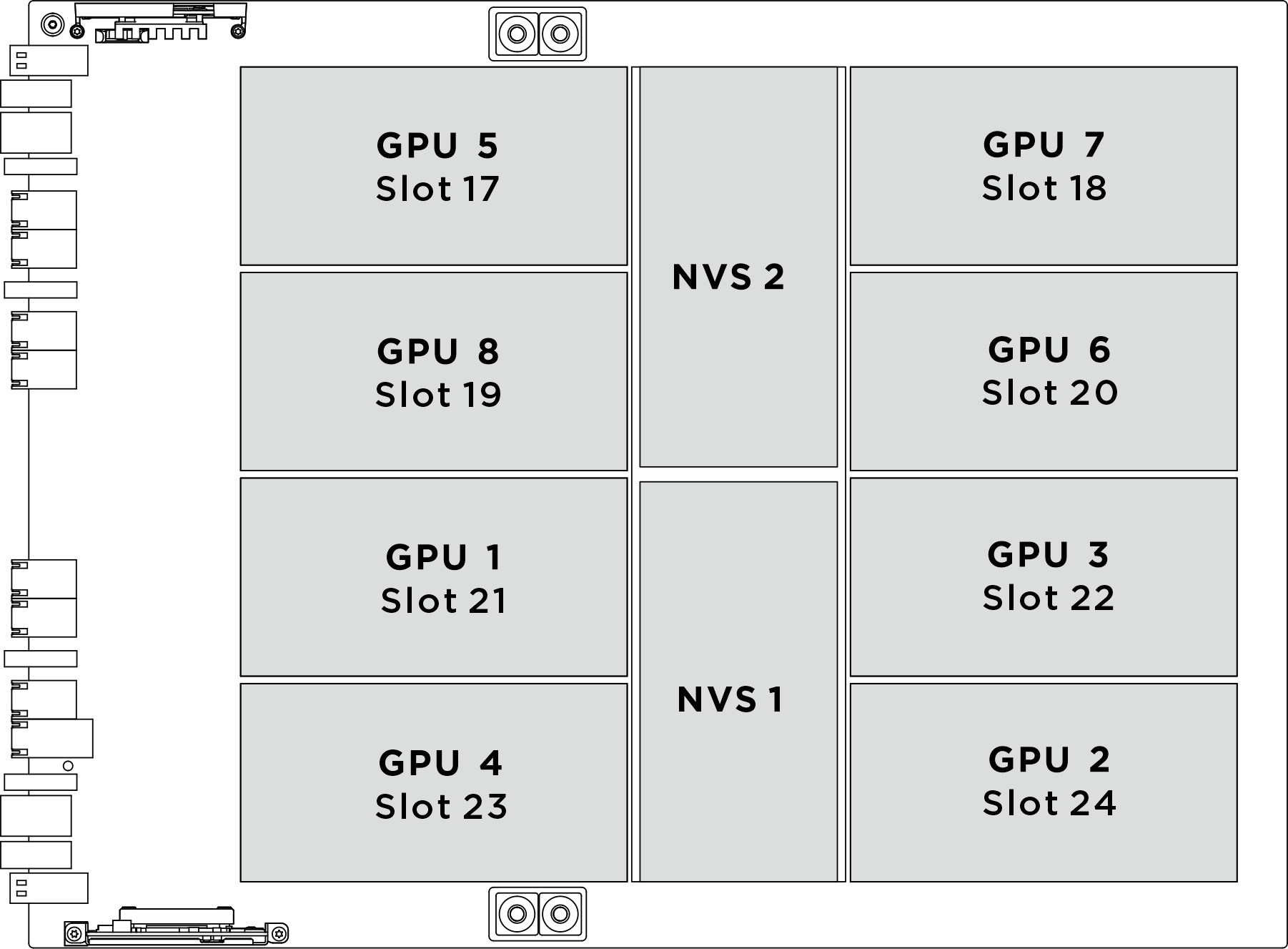
| Physischer GPU-Sockel | Steckplatznummerierung in XCC | Logische Nummer in nvidia-smi |
|---|---|---|
GPU 1 | Steckplatz 21 | 4 |
GPU 2 | Steckplatz 24 | 7 |
GPU 3 | Steckplatz 22 | 5 |
GPU 4 | Steckplatz 23 | 6 |
GPU 5 | Steckplatz 17 | 0 |
GPU 6 | Steckplatz 20 | 3 |
GPU 7 | Steckplatz 18 | 1 |
GPU 8 | Steckplatz 19 | 2 |
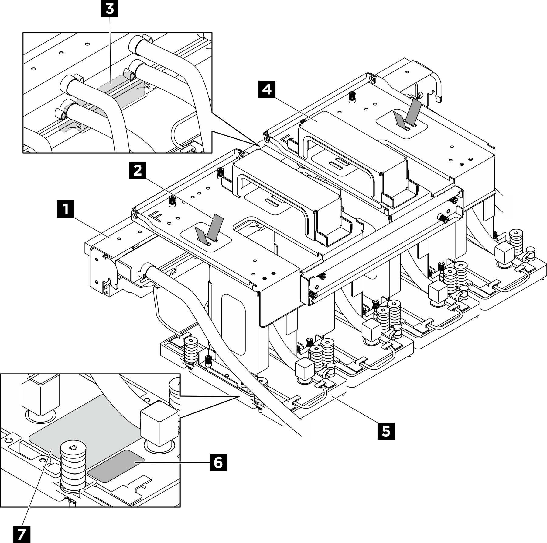
| 1 Leitung | 2 Schlauchbinder |
| 3 Flüssigkeitserkennungssensormodul | 4 Transporthalterung |
| 5 GPU-Kühlplatte | 6 Etikett der GPU-Steckplatznummer |
| 7 Drehmomentetikett für GPU-Kühlplattenschrauben |
Vorgehensweise
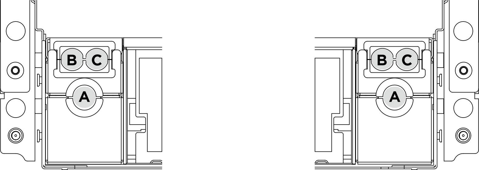
- Die folgende Abbildung zeigt die Position der Schlauchhalterung.Abbildung 3. Position der Schlauchhalterung
- Entfernen Sie die Halterung des hinteren Lüfterrahmens.
 Lösen Sie die acht M3-Schrauben, mit denen die Halterung des hinteren Lüfterrahmens am Gehäuse befestigt ist.
 Lösen Sie die vier M3-Schrauben, mit denen die Halterung für den hinteren Lüfterrahmen am Lüfterrahmen befestigt ist.
 Fassen Sie die Halterung des hinteren Lüfterrahmens, um sie aus dem Lüfterrahmen zu heben.
Abbildung 4. Entfernen der Halterung des hinteren Lüfterrahmens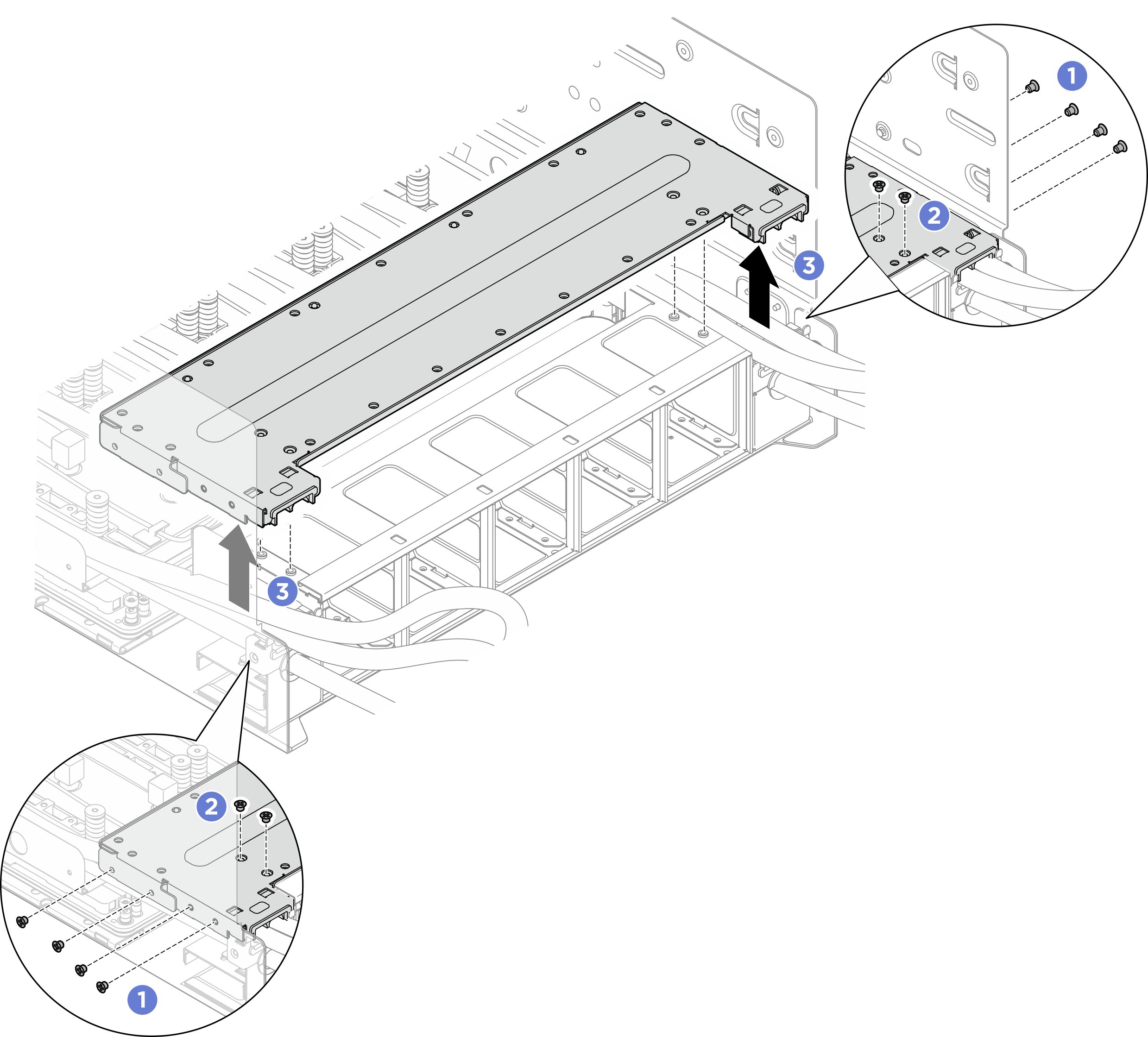
- Positionieren Sie die hintere B200 GPU-Kühlplattenleitung so, dass Platz für die vordere B200 GPU geschaffen wird. Installieren Sie die zwei Servicehalterungen an den hinteren GPU-Kühlplatten.
- Richten Sie die Führungsstifte an der Servicehalterung an den Führungslöchern auf der GPU-Kühlplatte aus. Senken Sie sie dann auf die Kühlplatte ab.
- Ziehen Sie die beiden unverlierbaren Schrauben (PH1, 2 x M3, 0,5 Newtonmeter bzw. 4,3 Poundforce Inch) an, um die Servicehalterung an der hinteren GPU-Kühlplatte zu installieren. Wiederholen Sie den Vorgang, um eine weitere Servicehalterung zu installieren.Abbildung 5. Installieren der Servicehalterungen an den hinteren GPU-Kühlplatten
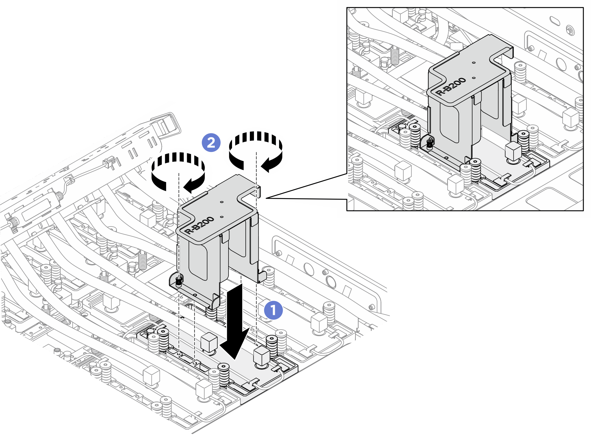 AnmerkungAchten Sie darauf, das Kabel des Flüssigkeitserkennungssensormodul beim Installieren der Halterung nicht einzuklemmen.
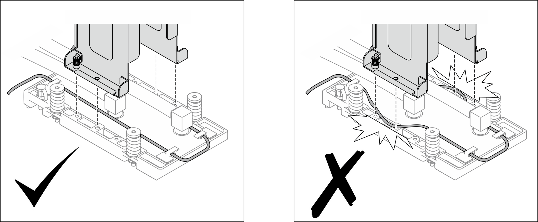
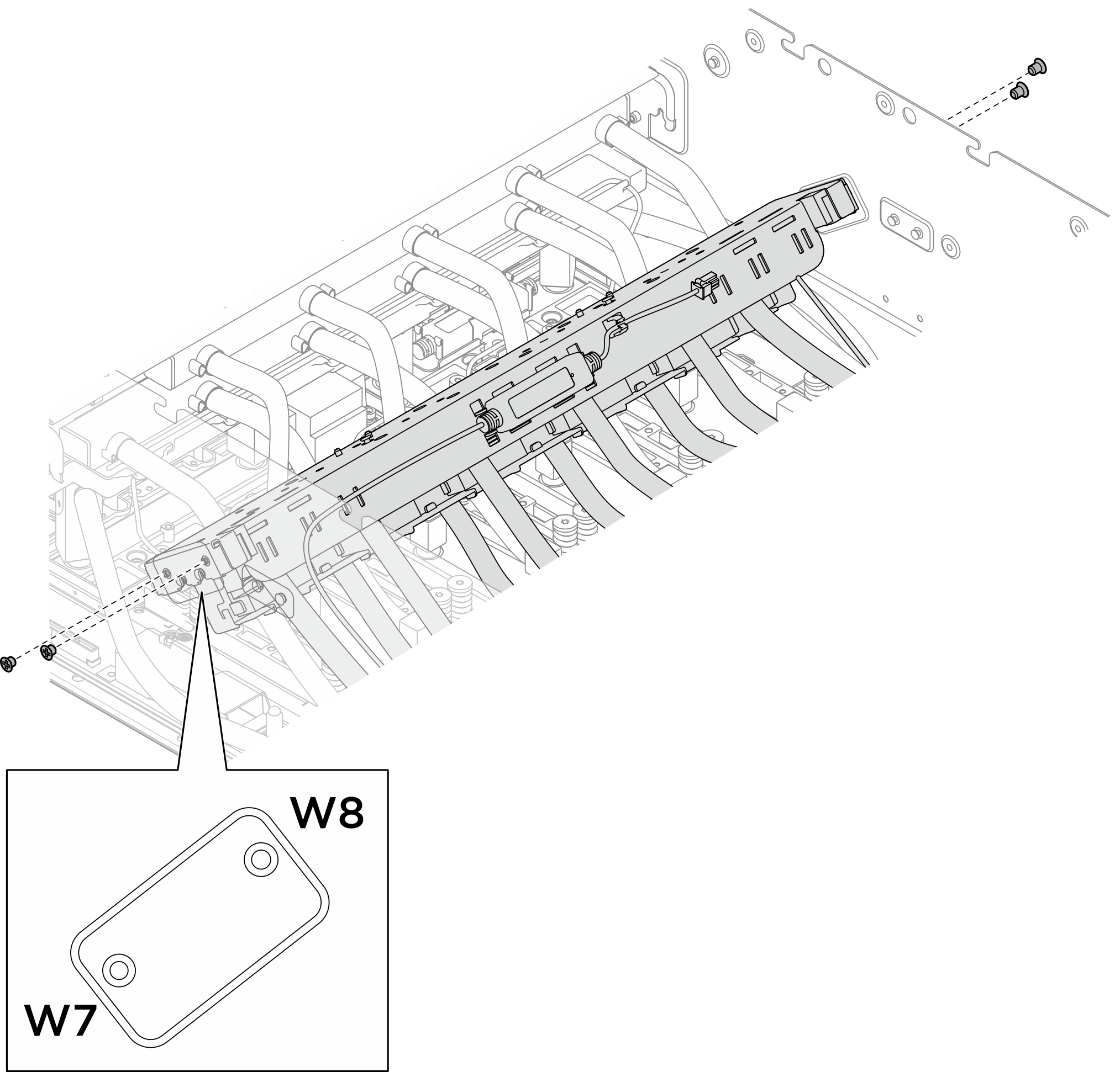
- Lösen Sie die vier M3-Schrauben (W7-W8), mit denen die Leitung des hinteren B200 GPU-Kühlplattenmoduls am Gehäuse befestigt ist.Abbildung 6. Entfernen der Leitung des hinteren B200 GPU-Kühlplattenmoduls
- Positionieren Sie die Leitung des hinteren B200 GPU-Kühlplattenmoduls neu.
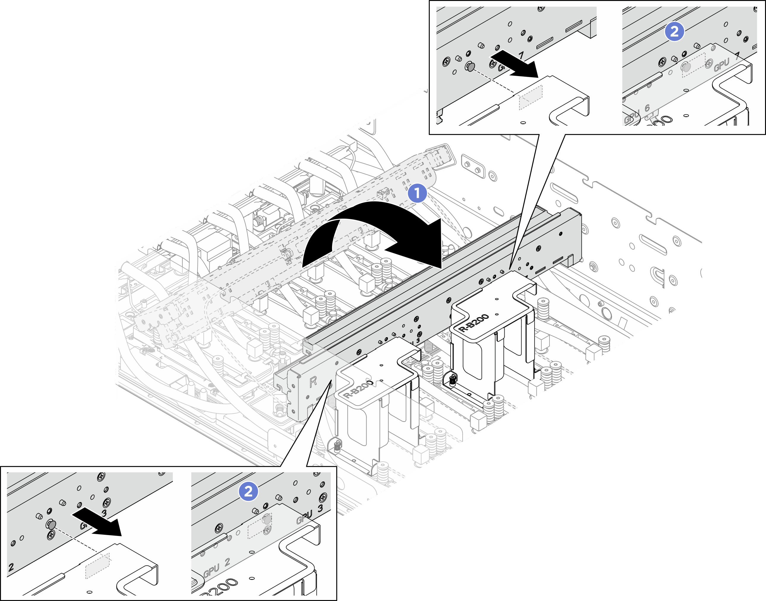
- Drehen Sie die Leitung des hinteren B200 GPU-Kühlplattenmoduls wie dargestellt um. Richten Sie die Führungsstifte auf der Leitung an den Führungsnuten der Transporthalterungen aus und setzen sie die Führungsstifte in die Nuten ein. Installieren Sie dann die Leitung wie dargestellt an den Servicehalterungen.
- Stellen Sie sicher, dass die Führungsstifte an der Leitung sicher in die Führungsnuten der Transporthalterungen eingerastet sind.Abbildung 7. Neupositionierung der Leitung des hinteren GPU-Kühlplattenmoduls
- Lösen Sie die Schrauben in der folgenden Schraubenreihenfolge um 360 Grad:
 (siehe Etikett der Kühlplatte). Lösen Sie dann die sechzehn T15-Torx-Schrauben mit einem Drehmomentschraubendreher und dem richtigen Drehmoment vollständig.Anmerkung
- Lösen Sie die Schrauben mit einem Drehmomentschraubendreher und dem richtigen Drehmoment. Das Drehmoment zum vollständigen Lösen oder Anziehen der Schrauben beträgt 5,3± 0,212Poundforce Inch bzw. 0,6± 0,024Newtonmeter.
- Stellen Sie sicher, dass die unverlierbaren Schrauben vollständig gelöst sind, bevor Sie das Kühlplattenmodul entfernen.
- Befolgen Sie die Schraubenreihenfolge, um ein Kippen der Kühlplatte zu verhindern.
Abbildung 8. Entfernen der GPU-Kühlplatten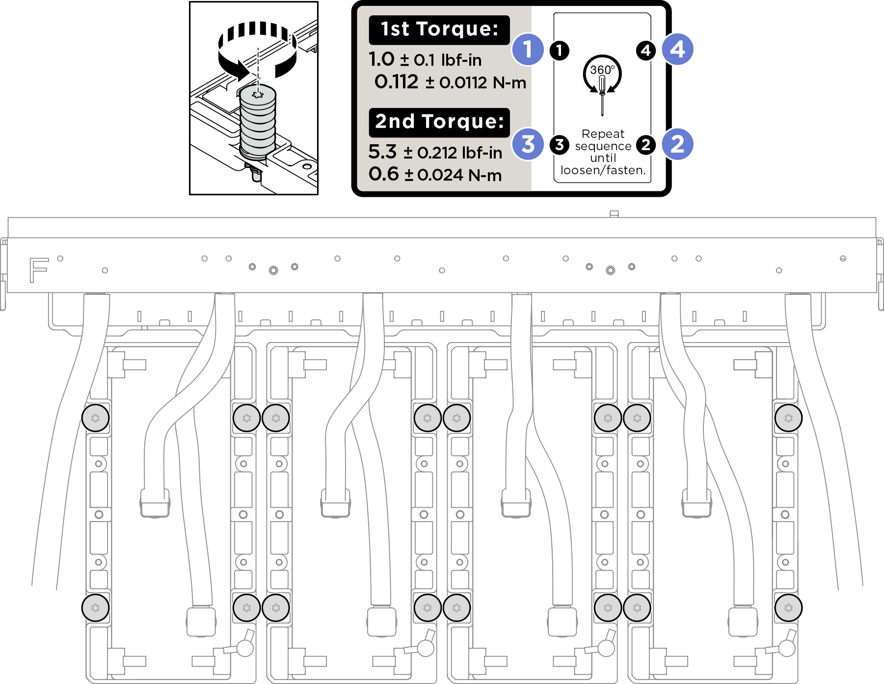 Anmerkung
Verwenden Sie die TIM-Trennschraube, falls erforderlich, um die Kühlplatte von der GPU zu trennen. Stellen Sie sicher, dass alle Schrauben der Kühlplatte vollständig gelöst sind, bevor Sie die TIM-Trennschraube anziehen.
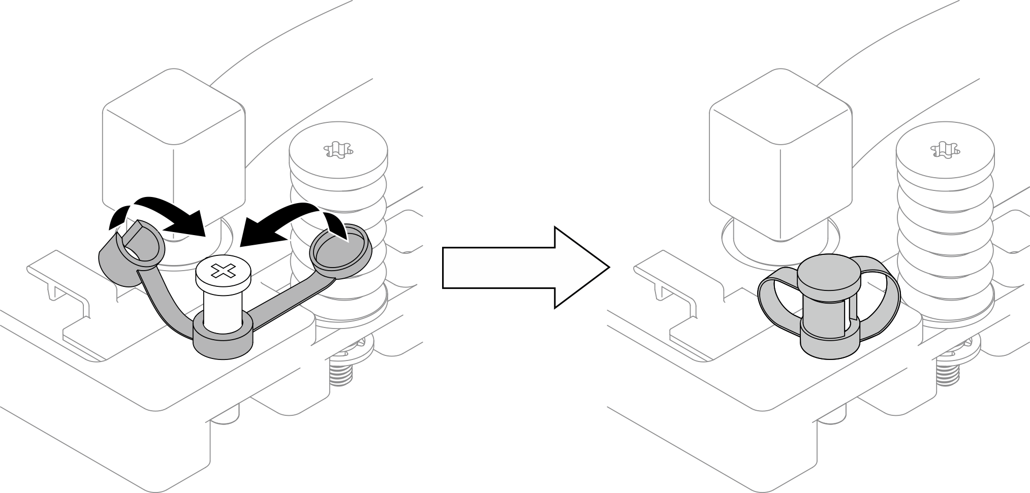
- Öffnen Sie den Deckel der TIM-Trennschraube.
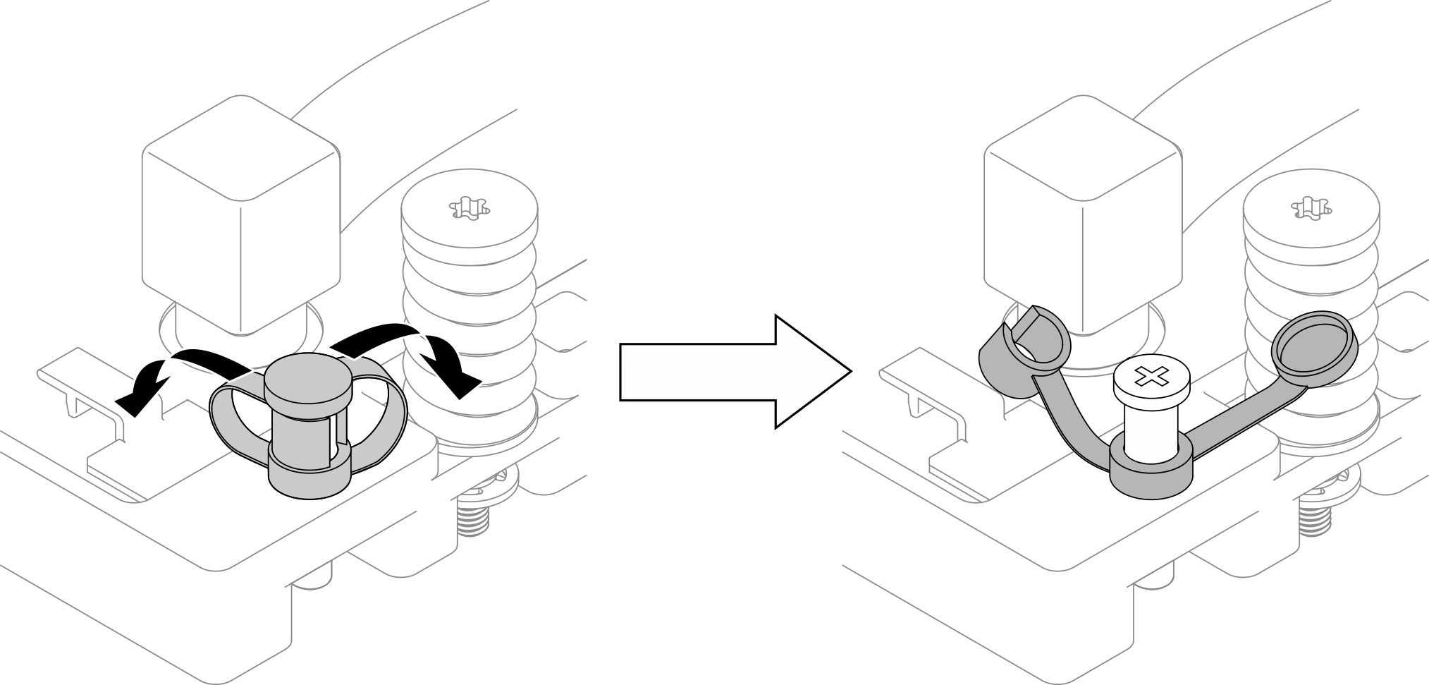
- Ziehen Sie die TIM-Trennschraube an, um die Kühlplatte von der GPU zu trennen.
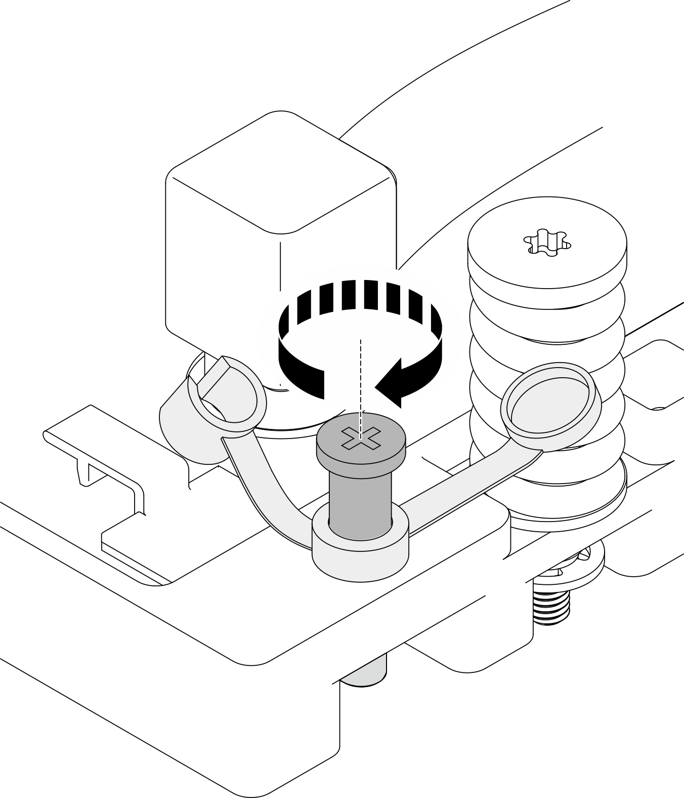
Bringen Sie die TIM-Trennschraube nach Gebrauch wieder in ihre ursprüngliche Position zurück.
- Lösen Sie die TIM-Trennschraube, um sie wieder in ihre ursprüngliche Position zu bringen.
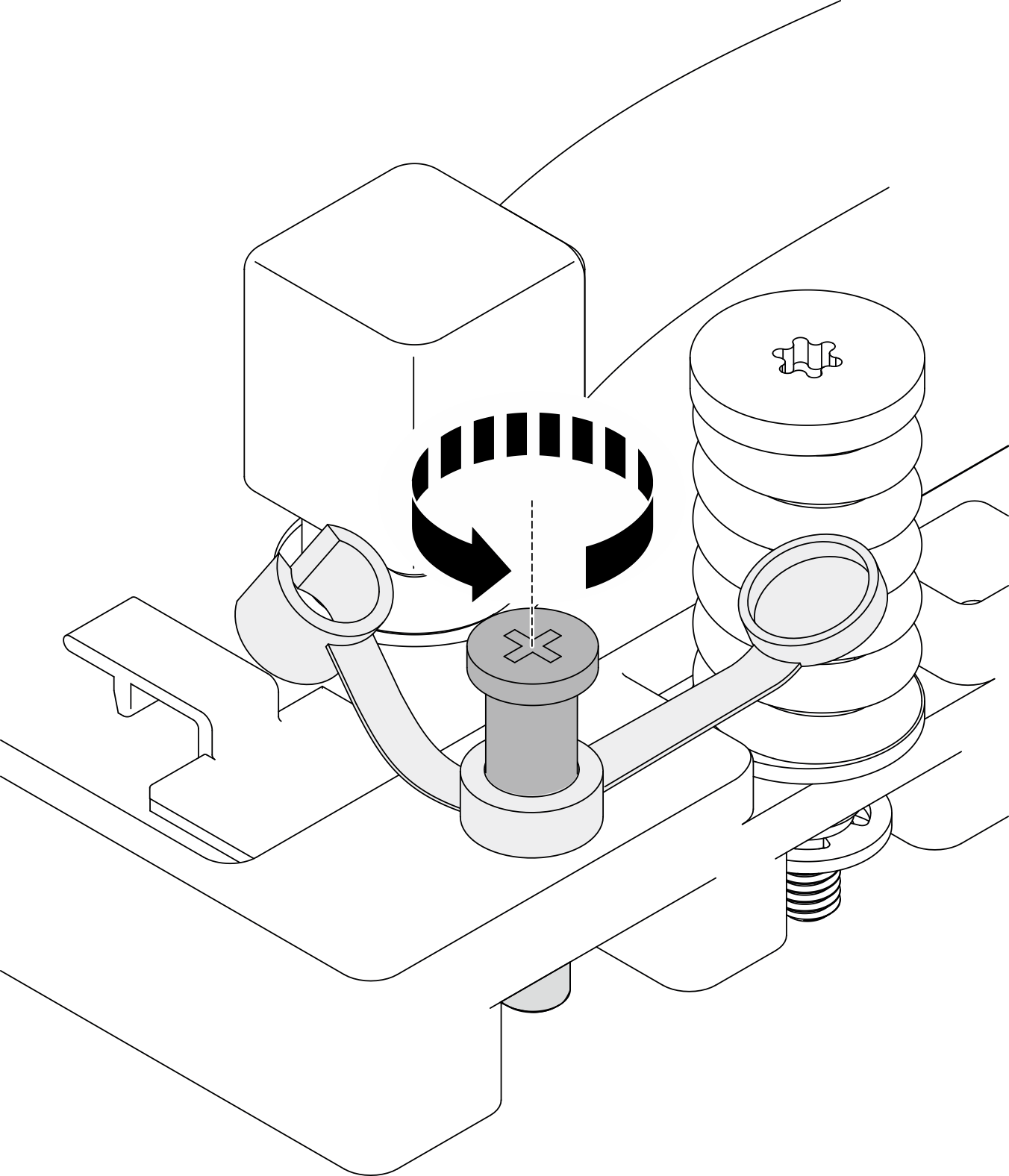
- Schließen Sie den Deckel. Wenn der Deckel nicht geschlossen werden kann, muss die TIM-Trennschraube weiter gelöst werden.
- Installieren Sie die Transporthalterungen.
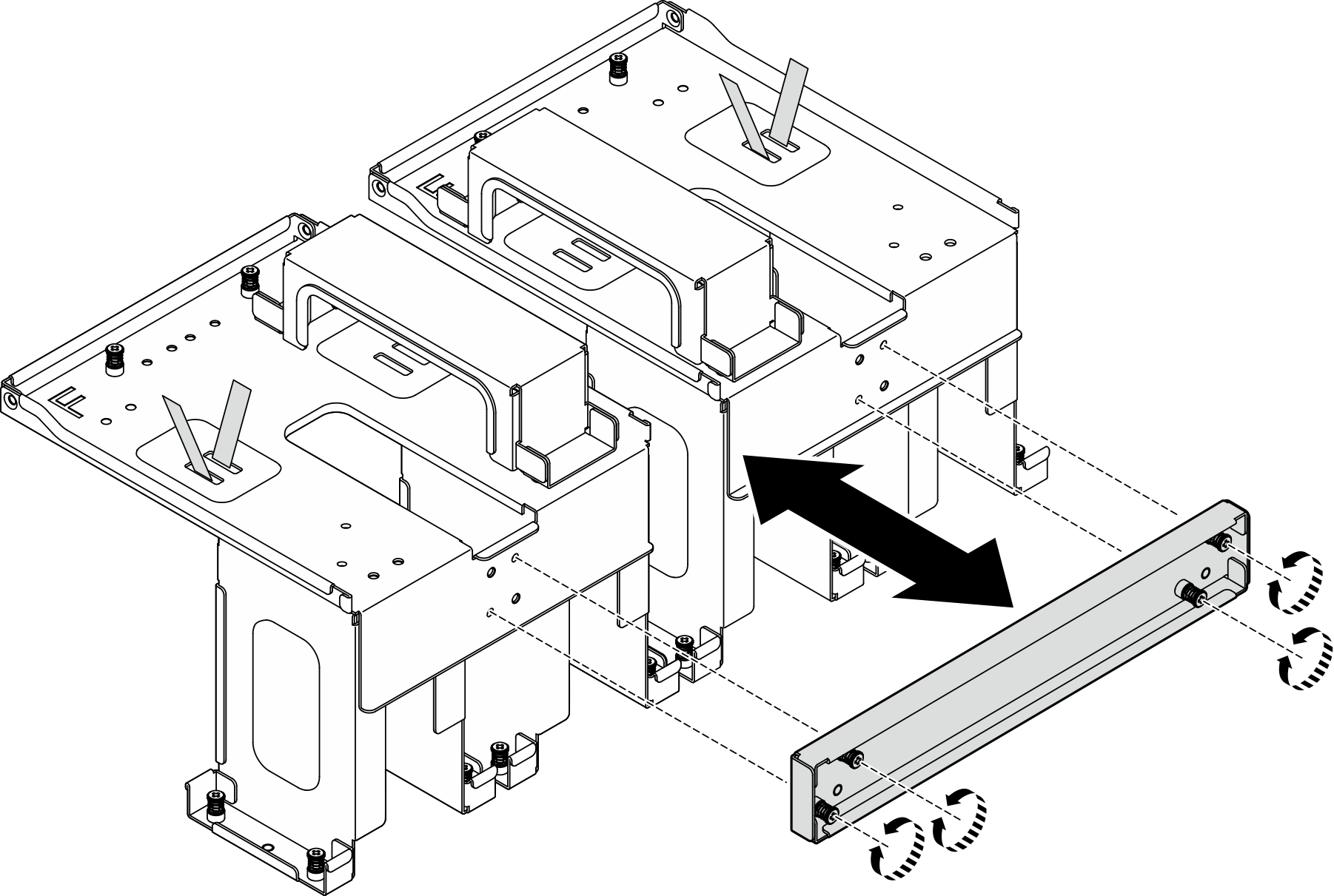
- Entfernen Sie die Querstrebe, bevor Sie die Transporthalterungen installieren. Lösen Sie die vier unverlierbaren Schrauben, um die Querstrebe zu entfernen.Abbildung 9. Entfernen der Querstrebe
- Richten Sie die Führungsstifte der Transporthalterungen an den Führungslöchern der Leitung und Kühlplatten aus. Senken Sie dann die Transporthalterungen auf das vordere B200 GPU-Kühlplattenmodul ab.
- Ziehen Sie die zehn unverlierbaren Schrauben (PH1, 10 x M3, 0,5 Newtonmeter bzw. 4,3 Poundforce Inch) an, um die Transporthalterung am vorderen B200 GPU-Kühlplattenmodul zu befestigen. Wiederholen Sie den Vorgang, um die andere Transporthalterung zu installieren.Abbildung 10. Installieren der Transporthalterungen
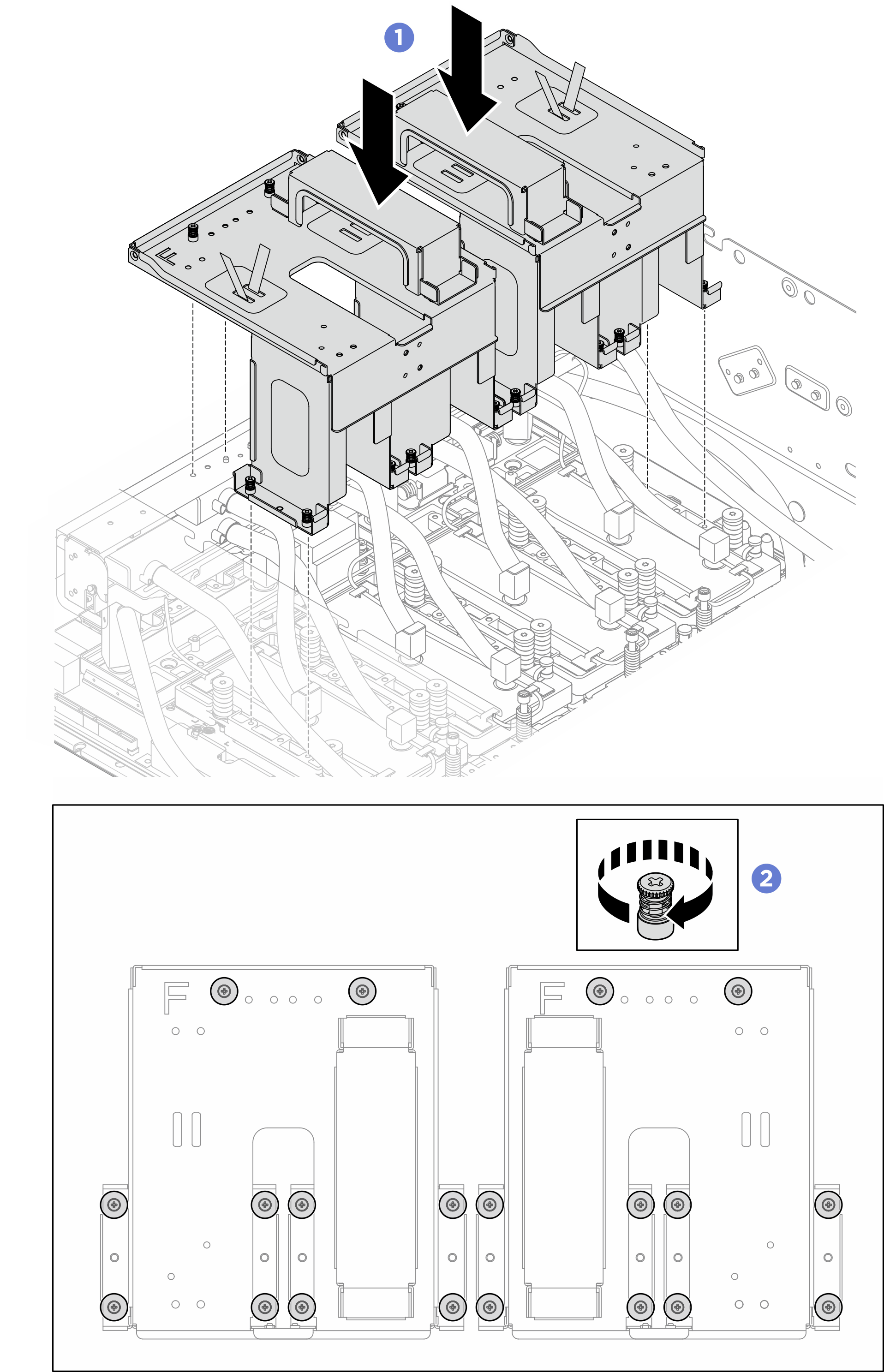 AnmerkungAchten Sie darauf, das Kabel des Flüssigkeitserkennungssensormodul beim Installieren der Halterung nicht einzuklemmen.
 - Installieren Sie die Querstrebe erneut. Richten Sie die Querstrebe an den Transporthalterungen aus. Ziehen Sie dann die vier unverlierbaren Schrauben an, um die Querstrebe an den Transporthalterungen zu installieren.Abbildung 11. Installieren der Querstrebe
- Entfernen Sie die Querstrebe, bevor Sie die Transporthalterungen installieren. Lösen Sie die vier unverlierbaren Schrauben, um die Querstrebe zu entfernen.
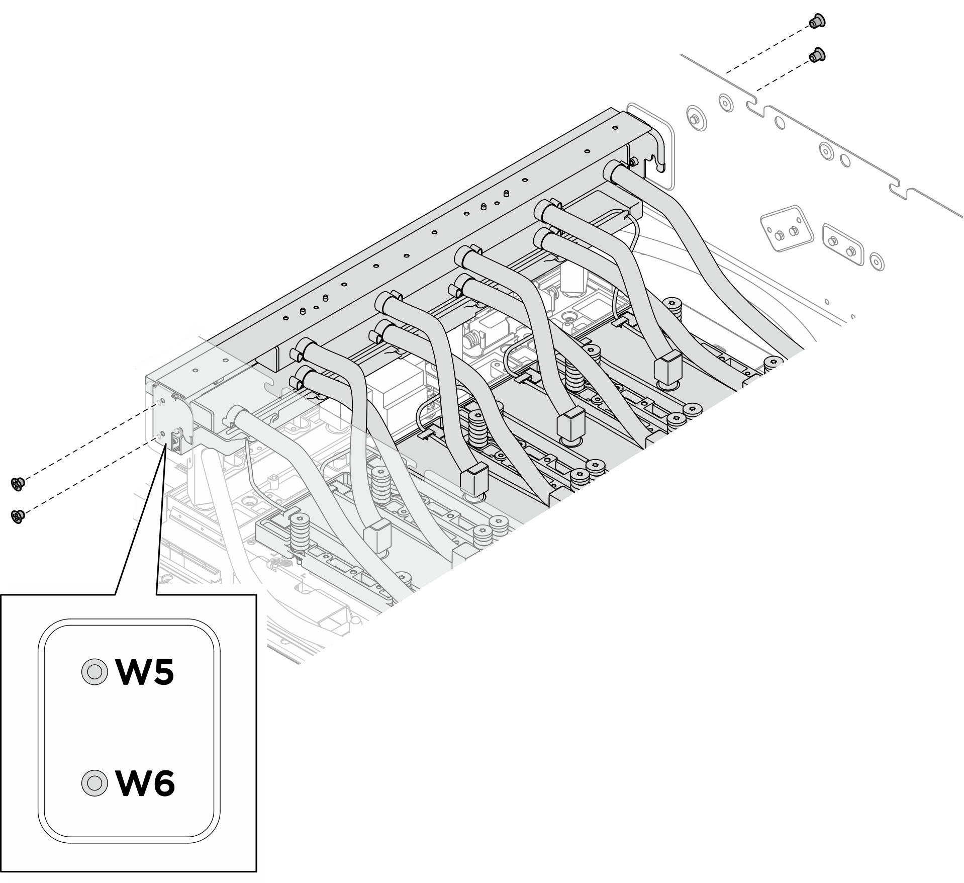
- Lösen Sie die vier M3-Schrauben (W5-W6), mit denen die Leitung des vorderen B200 GPU-Kühlplattenmoduls am Gehäuse befestigt ist.Abbildung 12. Entfernen der Leitung des vorderen B200 GPU-Kühlplattenmoduls
- Entfernen Sie das vordere B200 GPU-Kühlplattenmodul.
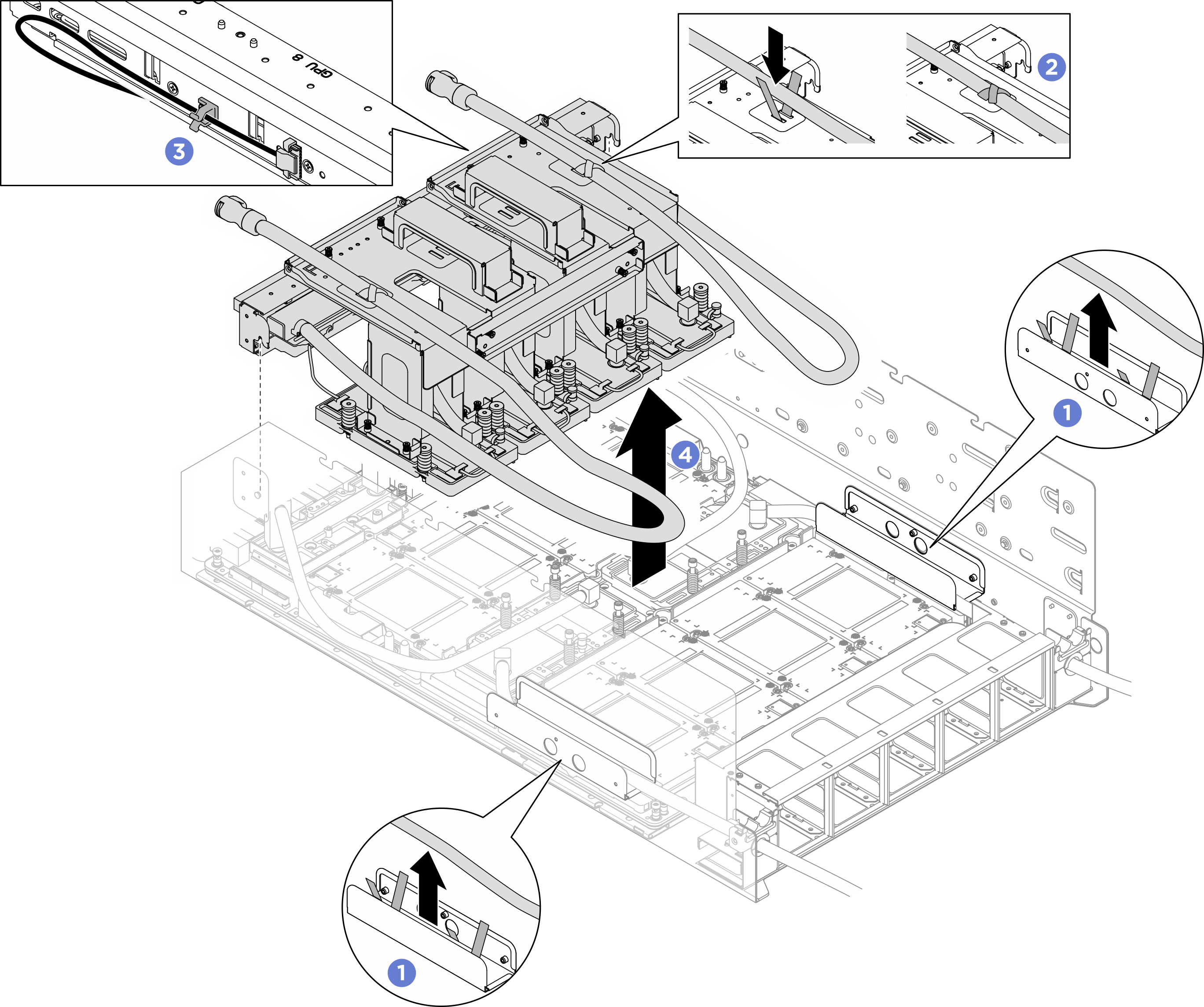
- Lösen Sie die Schläuche von den Schlauchbindern, mit denen sie an den Schlauchführungen befestigt sind.
- Befestigen Sie die Schläuche mit den Schlauchbindern an den Transporthalterungen.
- Befestigen Sie das Kabel des Flüssigkeitserkennungssensor mit der Kabelklemme an der Leitung.
- Halten Sie die Transporthalterungen und heben Sie das vordere B200 GPU-Kühlplattenmodul aus dem Gehäuse.Abbildung 13. Entfernen des vorderen B200 GPU-Kühlplattenmoduls
 AnmerkungWenn die Schrauben der Kühlplatte nicht vollständig gelöst sind, verwenden Sie den T15-Torx-Schraubendreher, um alle Schrauben der Kühlplatte vollständig zu lösen. Bringen Sie den T15-Torx-Verlängerungsbit (200mm) an, um bei Bedarf die Schrauben der Kühlplatte zu erreichen.
- Entfernen Sie PCM und Putty-Pads umgehend mit alkoholhaltigen Reinigungstüchern von den GPUs. Gehen Sie dabei sehr vorsichtig vor, um Beschädigungen an der GPU zu vermeiden.Achtung
Es wird empfohlen, das PCM zu entfernen, solange es in einem flüssigen Zustand ist.
Die elektrischen Komponenten rund um den Die (Chip) der GPUs sind äußerst empfindlich. Vermeiden Sie beim Entfernen des PCM und Reinigen des Die (Chip) der GPU, die elektrischen Komponenten zu berühren, um Schäden zu vermeiden.
Abbildung 14. Entfernen von PCM und Putty-Pads von den GPUs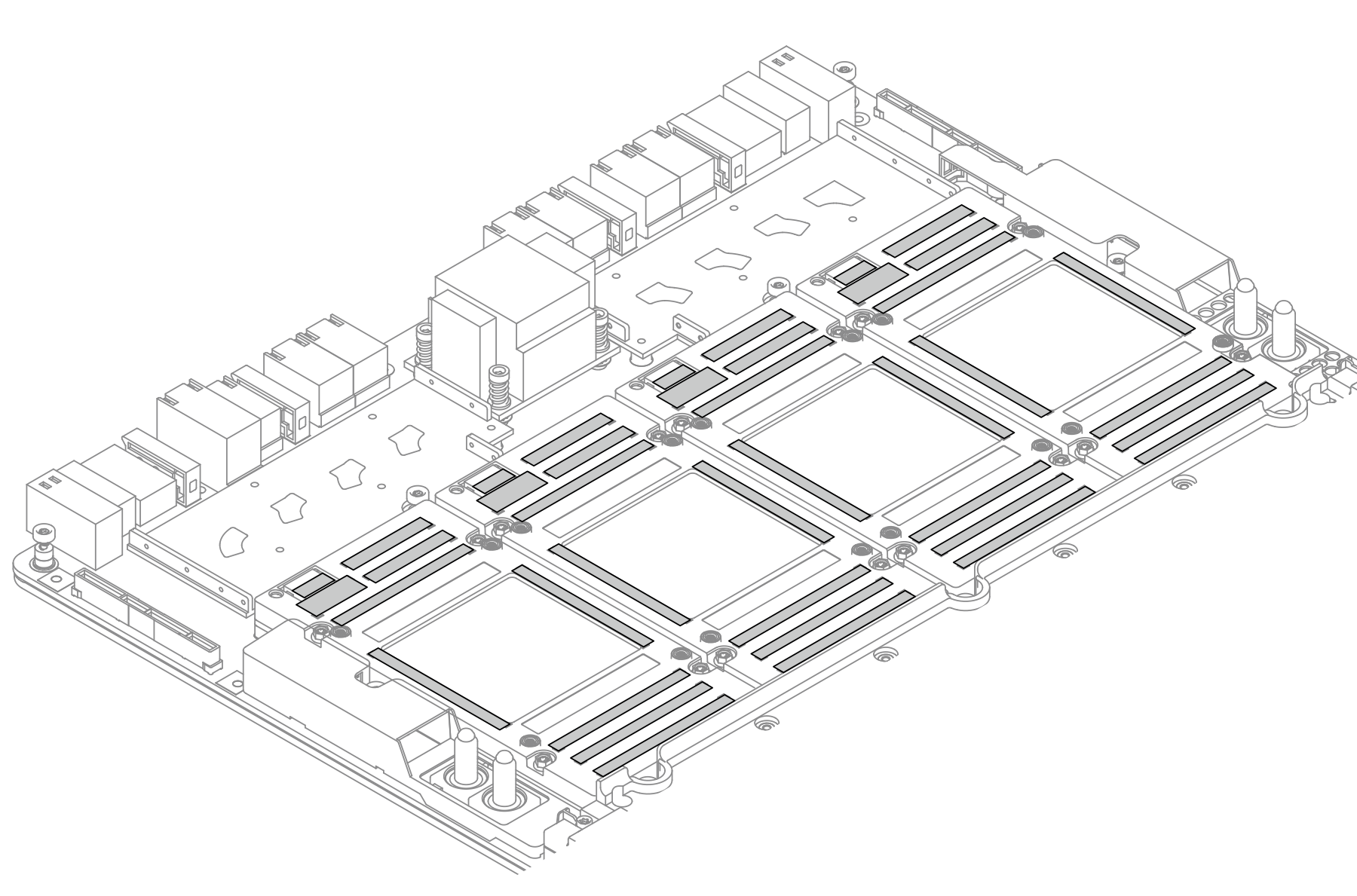
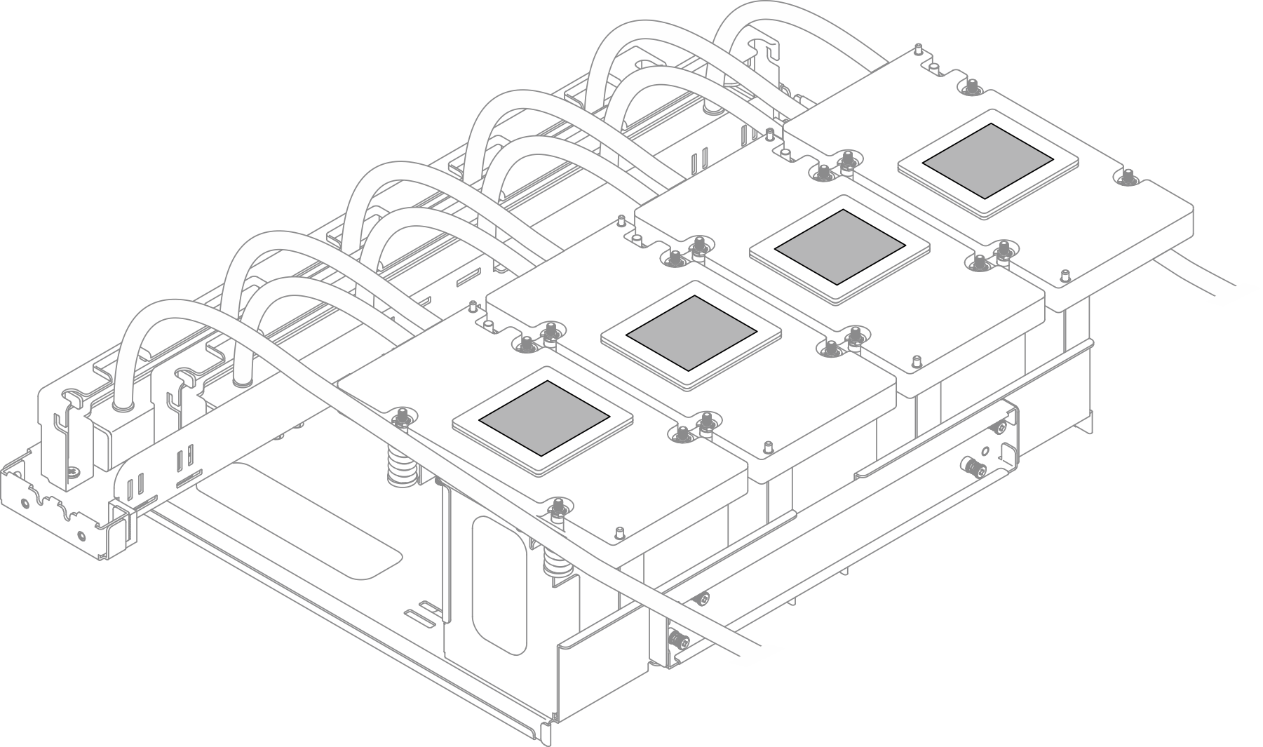
- Wischen Sie mit alkoholhaltigen Reinigungstüchern alle Reste des Putty-Pads und des PCM von der GPU-Kühlplatte ab.AnmerkungBewahren Sie die Transporthalterung am Kühlplattenmodul auf, falls sie später wieder installiert werden soll.Abbildung 15. Entfernen von PCM und Putty-Pads von den Kühlplatten
Nach dieser Aufgabe
- Installieren Sie eine Austauscheinheit. Siehe Vorderes B200 GPU-Kühlplattenmodul installieren.
- Wenn Sie angewiesen werden, die Komponente oder die Zusatzeinrichtung einzusenden, befolgen Sie die Verpackungsanweisungen und verwenden Sie ggf. das mitgelieferte Verpackungsmaterial für den Transport.