Remover a placa-base da GPU B200
Siga as instruções nesta seção para remover a placa-base da GPU B200. O procedimento deve ser executado por um técnico treinado.
Sobre esta tarefa
Atenção
- Leia Diretrizes de instalação e Lista de verificação de inspeção de segurança para garantir que esteja trabalhando de forma segura.
- Desligue o servidor e os dispositivos periféricos e desconecte os cabos de alimentação e todos os cabos externos. Consulte Desligar o servidor.
- Se o servidor estiver instalado em um rack, remova o servidor do rack. Consulte Remover o servidor do rack.
- Duas pessoas e um dispositivo de elevação no local que podem suportar até 400 lb (181 kg) são necessários para executar esse procedimento. Se você ainda não tiver um dispositivo de içamento disponível, a Lenovo oferece o Genie Lift GL-8 material lift que pode ser adquirido em Data Center Solution Configurator. Inclua o freio e a plataforma de carga ao pedir o Genie Lift GL-8 material lift.
Nota
Certifique-se de ter as ferramentas necessárias listadas abaixo disponíveis para substituir adequadamente o componente:
- Chave de fenda de cabeça Torx T15
- 2 x bit de extensão Torx T15 de 200 mm
- Chave de fenda de cabeça Phillips nº 1
- Chave de fenda de cabeça Phillips nº 2
- Pano de limpeza com álcool
- 2 x PCM B200
- 2 x B200 SXM6 PAD-1
- 2 x B200 SXM6 PAD-2
- Kit de suporte de remessa da GPU B200 F&R
- Kit de serviço de GPU B200
- Kit de serviço do NVSwitch da placa temporizadora B200
- Kit de envio do NVSwitch de placa temporizadora B200
- PCM NVSwitch B200
- NVSwitch B200 PAD-1
- NVSwitch B200 PAD-2
- Alça da placa-base da GPU B200
- Bit de extensão Torx T25 de 150 mm (para alças de placa-base de GPU)
Nota
Certifique-se de ter as ferramentas necessárias listadas abaixo disponíveis para substituir adequadamente o componente:
- Chave de fenda de torque que pode ser definida como 0,6 Newton-metro, 5,3 polegadas-libras
A ilustração a seguir mostra a numeração da GPU B200 e a numeração de slots correspondente no XCC.
Figura 1. Numeração da GPU B200
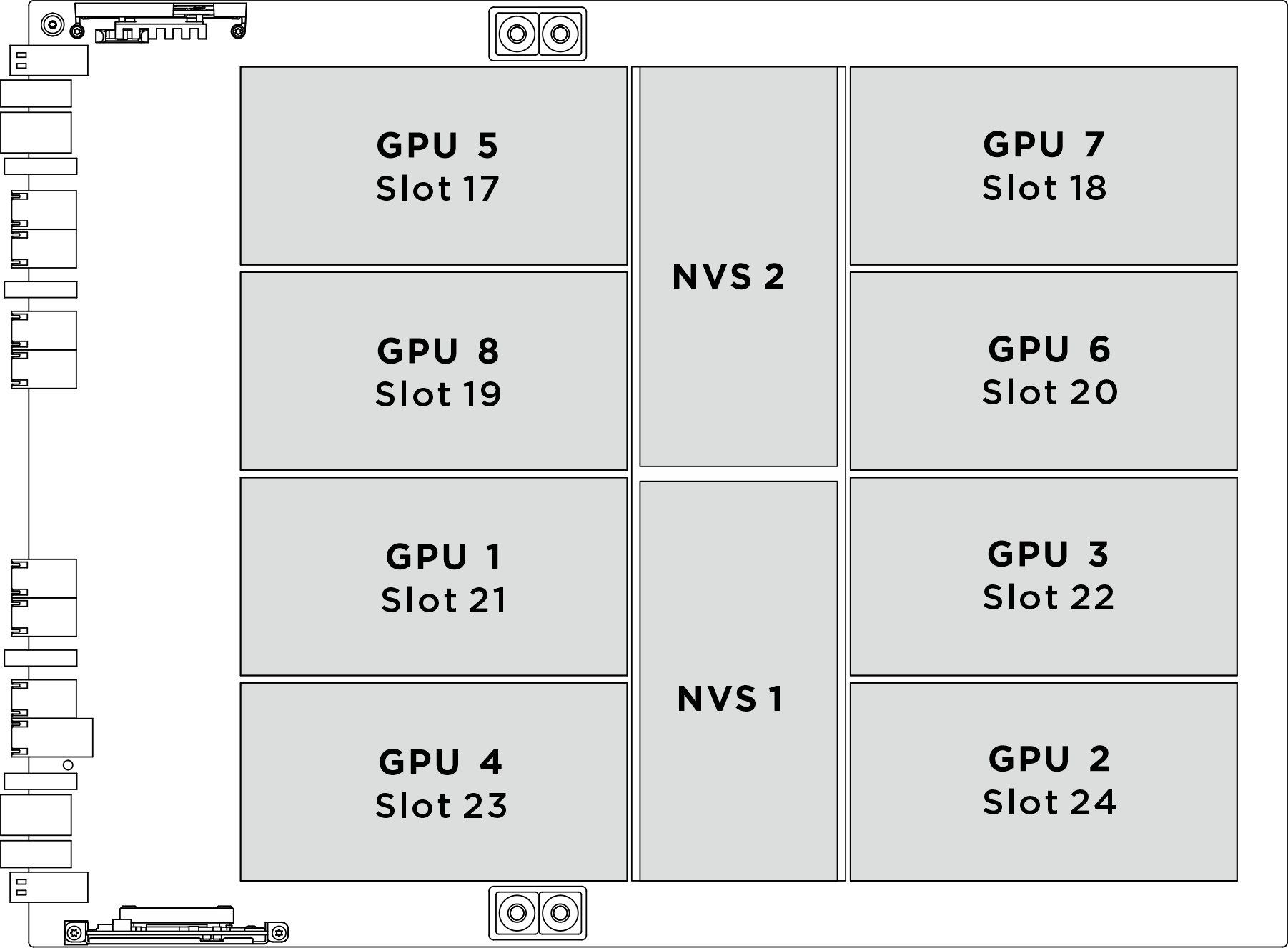
| Soquete de GPU físico | Numeração de slot no XCC | Número lógico em nvidia-smi |
|---|---|---|
GPU 1 | Slot 21 | 4 |
GPU 2 | Slot 24 | 7 |
GPU 3 | Slot 22 | 5 |
GPU 4 | Slot 23 | 6 |
GPU 5 | Slot 17 | 0 |
GPU 6 | Slot 20 | 3 |
GPU 7 | Slot 18 | 1 |
GPU 8 | Slot 19 | 2 |
Procedimento
- Desencaixe o alternador do comutador PCIe do chassi.
 Pressione as duas travas de liberação azuis.
 Gire as duas alavancas de liberação até que estejam perpendiculares ao alternador do comutador PCIe.
 Puxe o alternador do comutador PCIe para frente até que ele pare.ImportanteEmpurre as duas alavancas de liberação para trás até que elas travem no lugar depois de remover o alternador do comutador PCIe para evitar danos.Figura 2. Remoção do alternador do comutador PCIe para a posição de parada
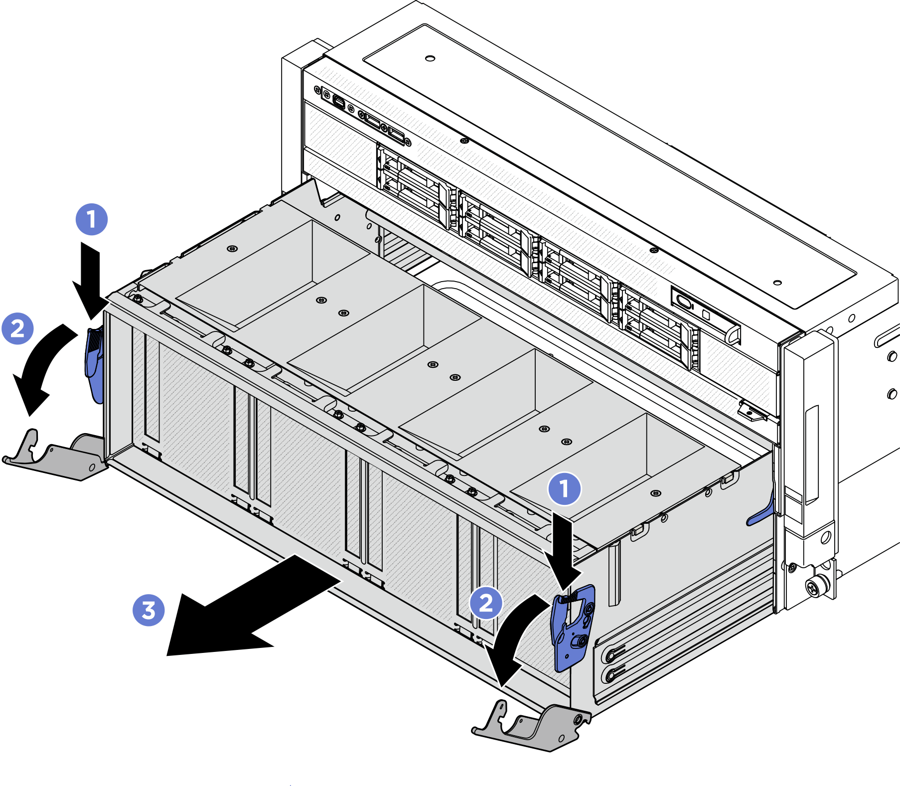
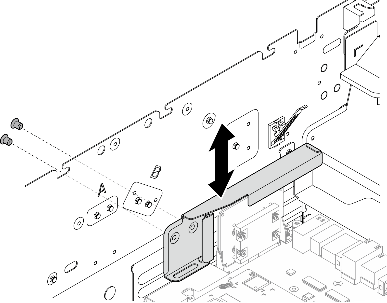
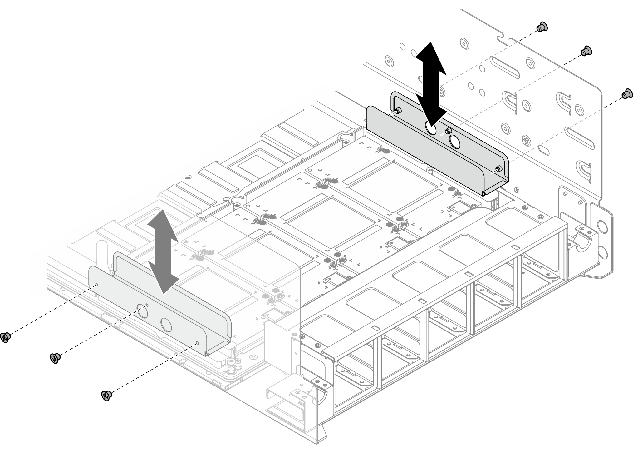
- Solte os dois parafusos M3 para remover o suporte de proteção do conector da GPU.Figura 3. Removendo o suporte de proteção do conector da GPU
- Solte os dois parafusos M3 para remover o suporte de proteção da placa do adaptador CX-7.Figura 4. Removendo o suporte de proteção da placa do adaptador CX-7
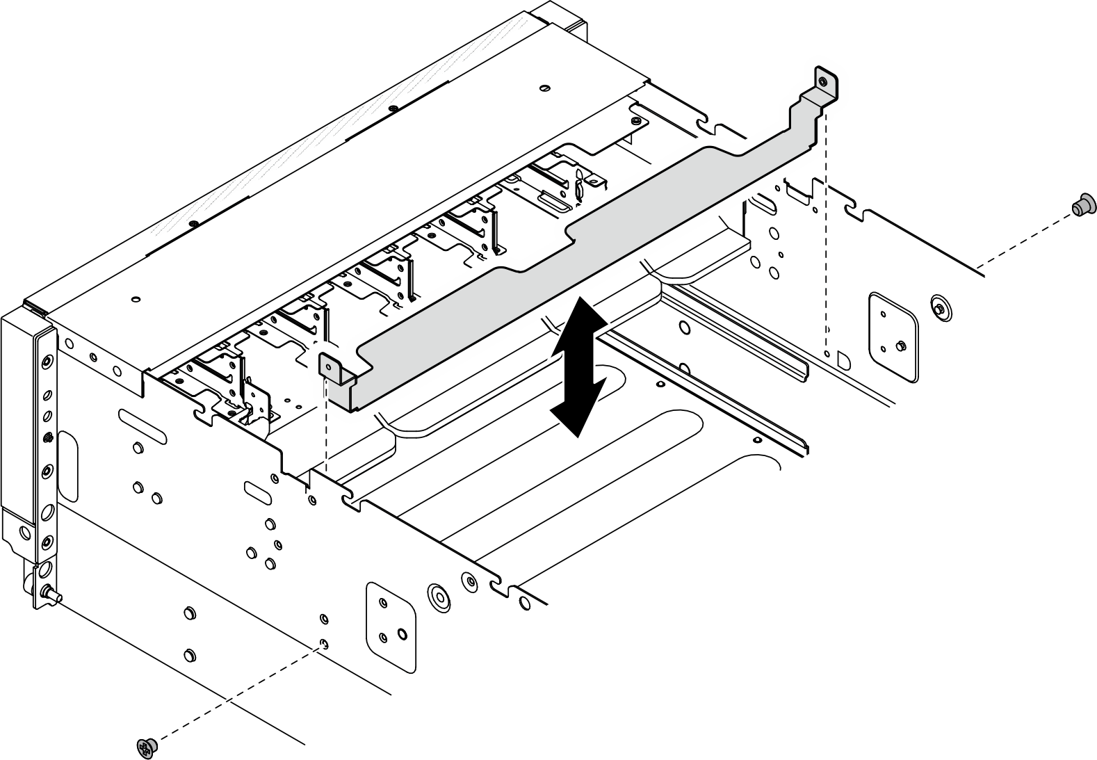
- Solte os três parafusos M3 para remover a guia da mangueira do chassi. Repita para remover a guia da mangueira do outro lado.Figura 5. Removendo a guia da mangueira
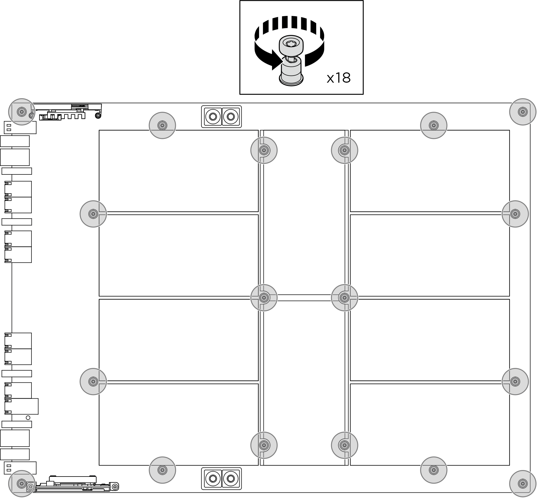
- Solte os dezoito parafusos prisioneiros Torx T15 na placa-base da GPU.NotaSolte ou aperte os parafusos com uma chave de fenda de torque ajustada para o torque adequado. Para referência, o torque necessário para que os parafusos fiquem totalmente soltos ou presos é de 0,6±0,024 Newton-metro, de 5,3±0,212 libras-polegada.Figura 6. Remoção do parafuso
- Remova o complexo da GPU.
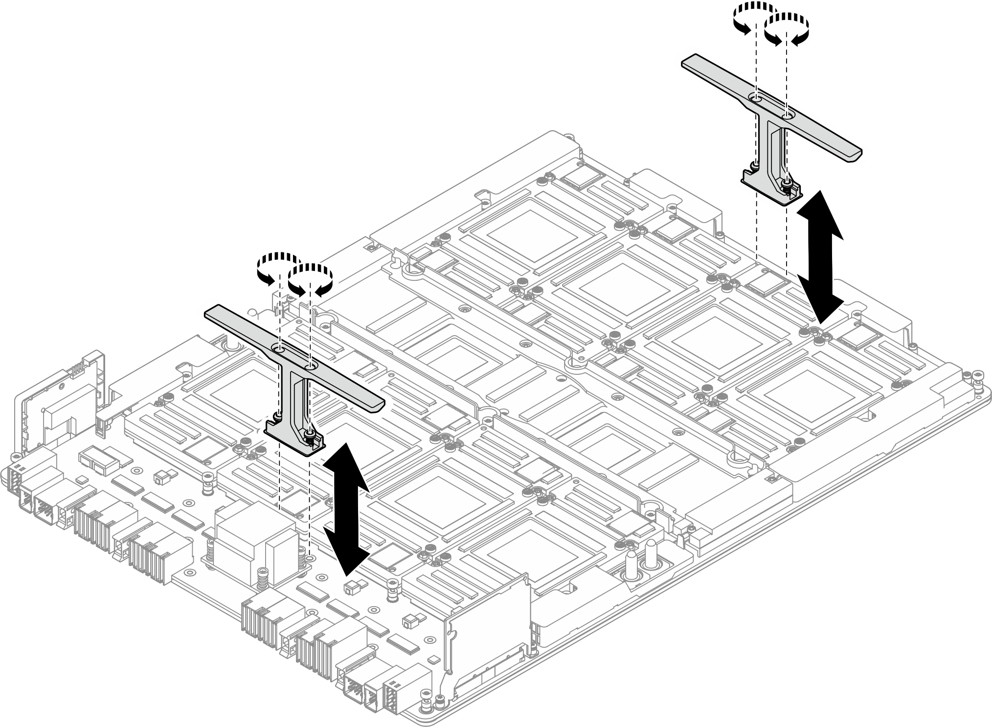
- Instale as alças. Conecte o bit de extensão Torx T25 à chave de fenda. Alinhe as alças com os orifícios dos parafusos e abaixe-as na placa-base da GPU; em seguida, aperte os quatro parafusos M4 (4 x M4, 0,5 Newton-metro, 4,3 polegadas-libra) para prender as alças na placa-base da GPU.Figura 7. Instalando as alças
- Segure as duas alças (1) e levante o complexo da GPU para fora do chassi.
AtençãoDuas pessoas devem estar em cada lado do complexo da GPU e levantá-lo segurando as duas alças.Figura 8. Removendo o complexo da GPU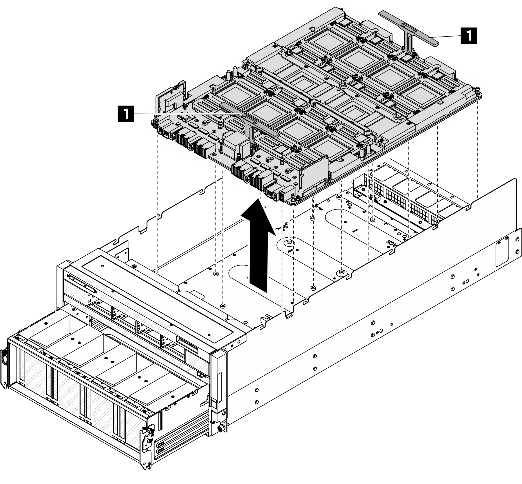 NotaMantenha as alças conectadas ao complexo da GPU se ele for enviado para o procedimento de RMA.
 - Remova as alças se necessário. Coloque com cuidado o complexo da GPU em uma superfície protetora plana e estática; em seguida, conecte o bit de extensão Torx T25 à chave de fenda e solte os quatro parafusos M4 que prendem as alças à placa-base. Levante as alças para removê-las da placa-base.NotaMantenha as alças conectadas ao complexo da GPU se ele for enviado para o procedimento de RMA.Figura 9. Removendo as alças
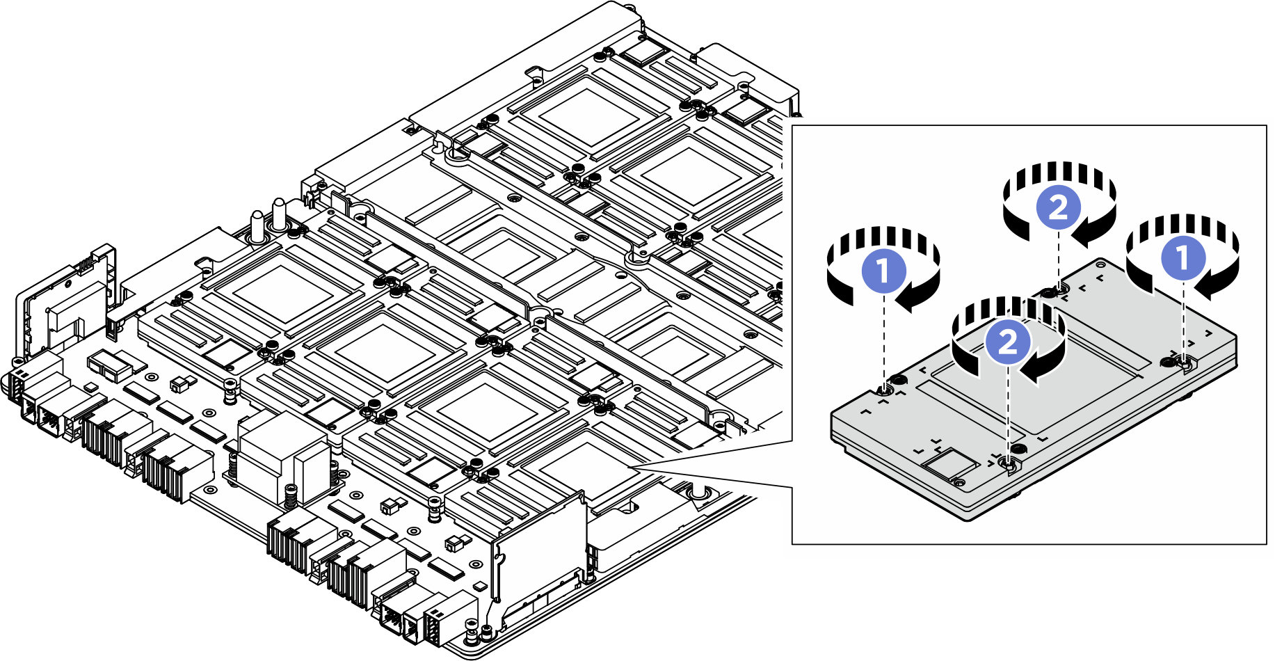
- Remova as GPUs da placa-base da GPU. Solte simultaneamente os dois parafusos Torx T15 diagonais com a chave de fenda ajustada para o torque adequado.
- Ajuste a chave de fenda de torque para 0,6 Newton-metro, 5,3 libras-polegada para soltar simultaneamente os dois parafusos diagonais ; em seguida, solte simultaneamente os dois parafusos diagonais .Figura 10. Removendo a GPU
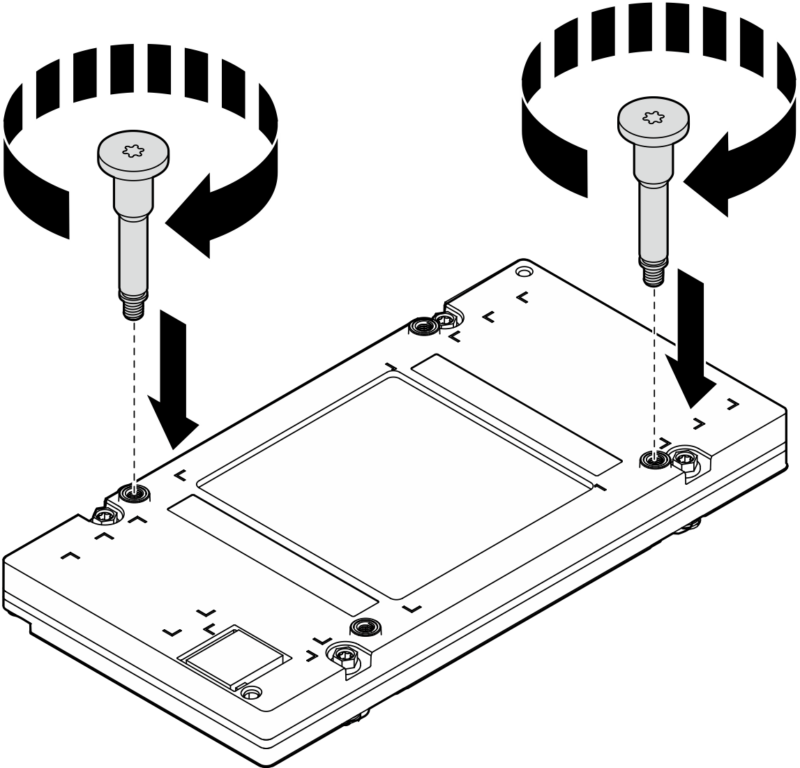
- Instale as duas alças com rosca da GPU na diagonal. Alinhe as alças dos parafusos aos slots dos parafusos da placa fria; em seguida, aperte as alças dos parafusos com a mão.Figura 11. Instalando as alças com rosca da GPU
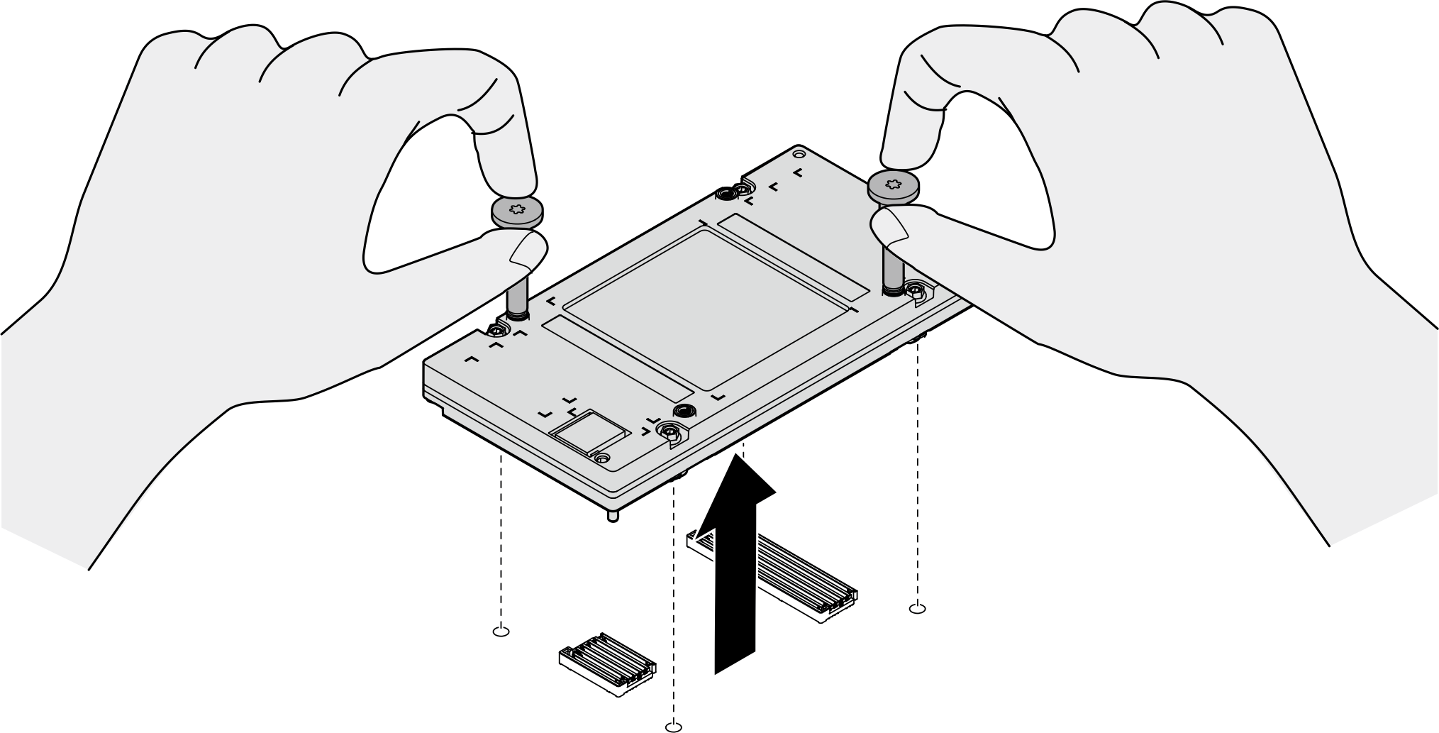
- Segure as alças dos parafusos da GPU para remover a GPU da respectiva placa-base.Figura 12. Removendo a GPU
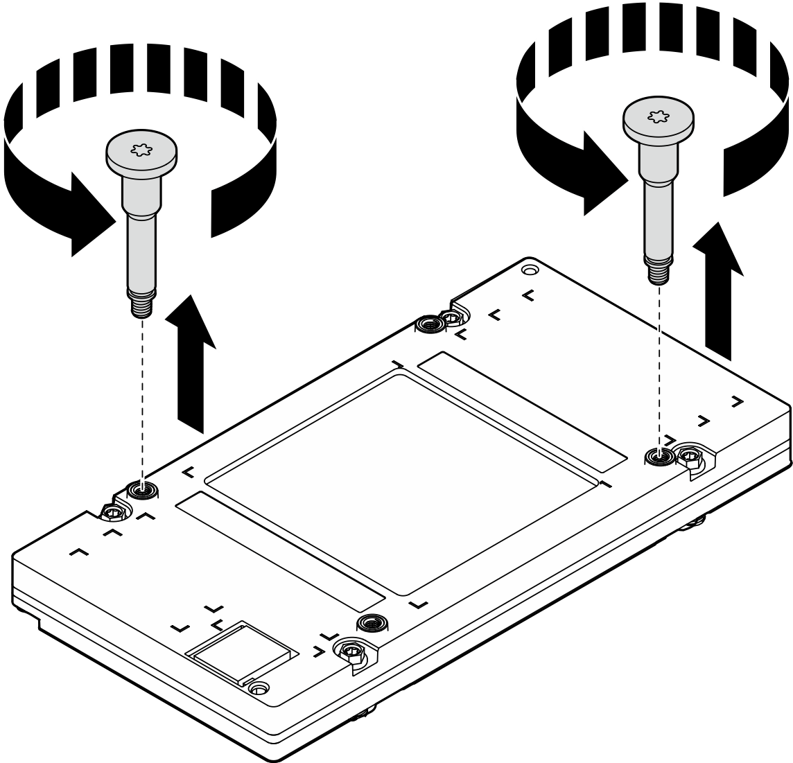
- Cuidadosamente, coloque a GPU em uma superfície protetora plana e estática. Remova as duas alças com rosca soltando-as com as mãos.Figura 13. Removendo as alças com rosca da GPU
- Ajuste a chave de fenda de torque para 0,6 Newton-metro, 5,3 libras-polegada para soltar simultaneamente os dois parafusos diagonais
Depois de concluir
- Instale uma unidade de substituição. Consulte Instalar a placa-base da GPU B200.
- Se você receber instruções para retornar o componente ou o dispositivo opcional, siga todas as instruções do pacote e use os materiais do pacote para remessa que foram fornecidos.
Enviar feedback