Independent memory mode
In independent memory mode, memory channels can be populated with DIMMs in any order and you can populate all channels for each processor in any order with no matching requirements. Independent memory mode provides the highest level of memory performance, but lacks failover protection. The DIMM installation order for independent memory mode varies based on the number of processors and memory modules installed in the server.
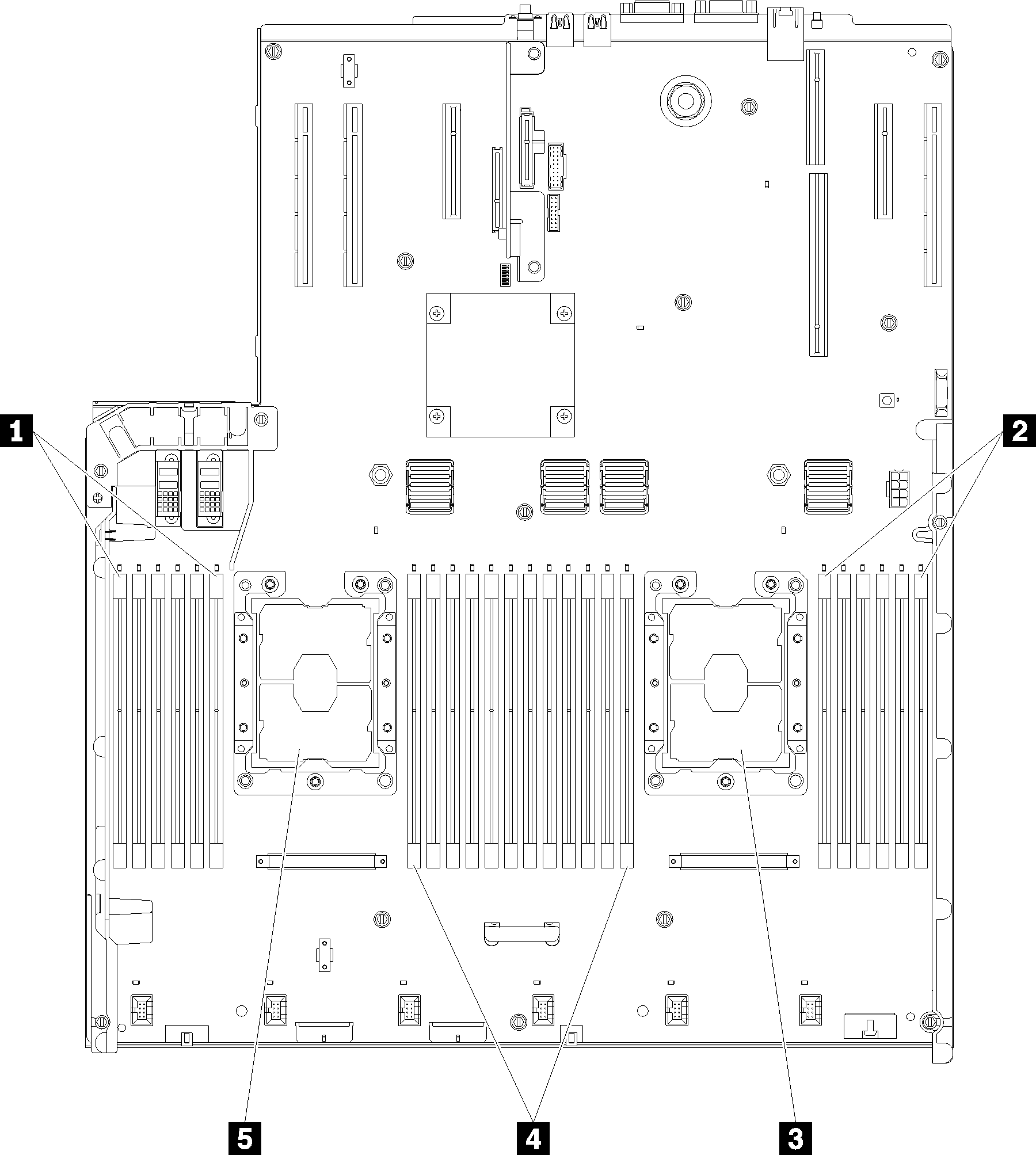
| 1 DIMM 1-6 | 4 DIMM 7-18 |
| 2 DIMM 19-24 | 5 Processor 1 |
| 3 Processor 2 |
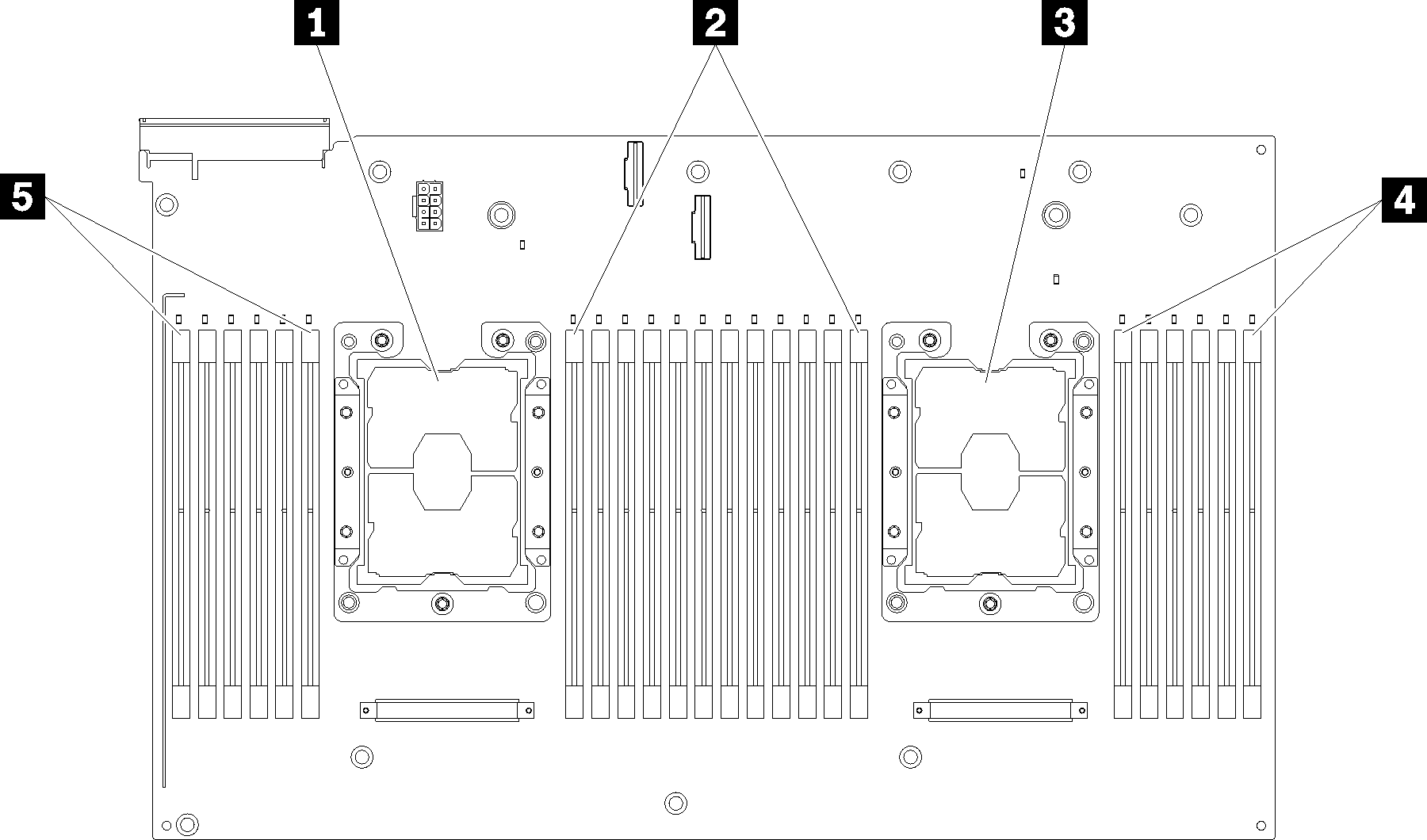
| 1 Processor 3 | 4 DIMM 43-48 |
| 2 DIMM 31-42 | 5 DIMM 25-30 |
| 3 Processor 4 |
| Slot | 0 | 1 | 0 | 1 | 0 | 1 | Processor | 1 | 0 | 1 | 0 | 1 | 0 | ||
| Channel | Channel 2 | Channel 1 | Channel 0 | Channel 0 | Channel 1 | Channel 2 | |||||||||
| DIMM number (Processor 1) | 1 | 2 | 3 | 4 | 5 | 6 | 7 | 8 | 9 | 10 | 11 | 12 | |||
| DIMM number (Processor 2) | 13 | 14 | 15 | 16 | 17 | 18 | 19 | 20 | 21 | 22 | 23 | 24 | |||
| DIMM number (Processor 3) | 25 | 26 | 27 | 28 | 29 | 30 | 31 | 32 | 33 | 34 | 35 | 36 | |||
| DIMM number (Processor 4) | 37 | 38 | 39 | 40 | 41 | 42 | 43 | 44 | 45 | 46 | 47 | 48 | |||
Individual memory channels can run at different DIMM timings, but all channels must run at the same interface frequency.
Populate memory channel 0 first.
Memory channel 1 is empty or identically populated as memory channel 0.
Memory channel 2 is empty or identically populated as memory channel 1.
In each memory channel, populate slot 0 first.
If a memory channel has two DIMMs, populate the DIMM with a higher number of ranks in slot 0.