Memory mirroring mode
Memory-mirroring mode provides full memory redundancy while reducing the total system memory capacity in half. Memory channels are grouped in pairs with each channel receiving the same data. If a failure occurs, the memory controller switches from the DIMMs on the primary channel to the DIMMs on the backup channel. The DIMM installation order for memory mirroring varies based on the number of processors and DIMMs installed in the server.
Memory mirroring reduces the maximum available memory by half of the installed memory. For example, if the server has 64 GB of installed memory, only 32 GB of addressable memory is available when memory mirroring is enabled.
Each DIMM must be identical in size and architecture.
DIMMs on each memory channel must be of equal density.
If two memory channels have DIMMs, mirroring occurs across two DIMMs (channels 0/1 will both contain the primary/secondary memory caches).
If three memory channels have DIMMs, mirroring occurs across all three DIMMs (channels 0/1, channels 1/2, and channels 2/0 will all contain primary/secondary memory caches).
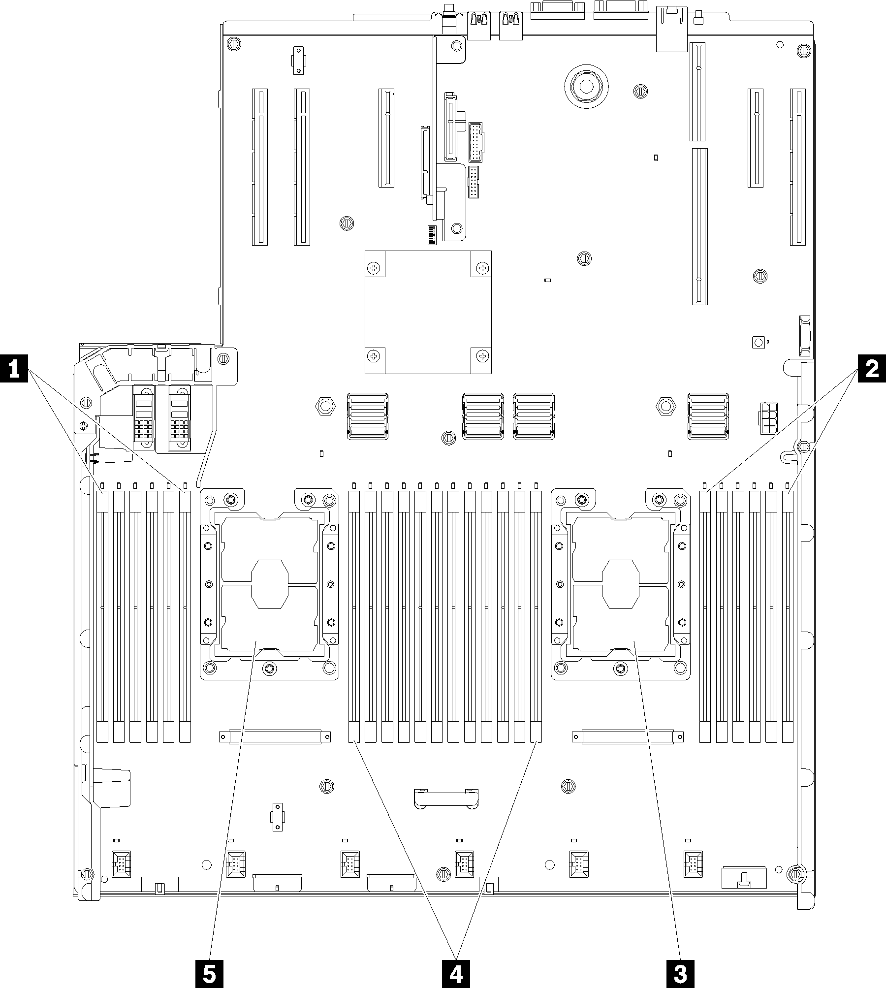
| 1 DIMM 1-6 | 4 DIMM 7-18 |
| 2 DIMM 19-24 | 5 Processor 1 |
| 3 Processor 2 |
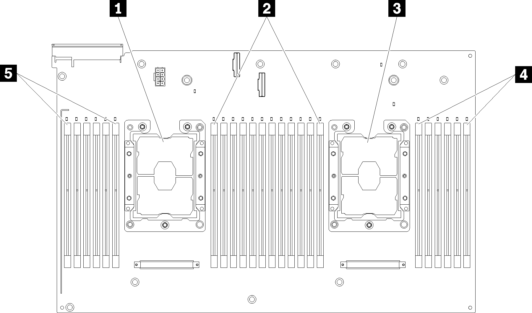
| 1 Processor 3 | 4 DIMM 43-48 |
| 2 DIMM 31-42 | 5 DIMM 25-30 |
| 3 Processor 4 |
| Slot | 0 | 1 | 0 | 1 | 0 | 1 | Processor | 1 | 0 | 1 | 0 | 1 | 0 | ||
| Channel | Channel 2 | Channel 1 | Channel 0 | Channel 0 | Channel 1 | Channel 2 | |||||||||
| DIMM number (Processor 1) | 1 | 2 | 3 | 4 | 5 | 6 | 7 | 8 | 9 | 10 | 11 | 12 | |||
| DIMM number (Processor 2) | 13 | 14 | 15 | 16 | 17 | 18 | 19 | 20 | 21 | 22 | 23 | 24 | |||
| DIMM number (Processor 3) | 25 | 26 | 27 | 28 | 29 | 30 | 31 | 32 | 33 | 34 | 35 | 36 | |||
| DIMM number (Processor 4) | 37 | 38 | 39 | 40 | 41 | 42 | 43 | 44 | 45 | 46 | 47 | 48 | |||