Remove the operator panel tray assembly
Use this procedure to remove the operator panel tray assembly.
Before removing the operator panel tray assembly:
Read the safety information and installation guidelines (see Safety and Installation Guidelines).
Turn off the server and peripheral devices and disconnect the power cords and all external cables (see Power off the server).
If the server is installed in a rack, remove the server from the rack.
Remove the top cover (see Remove the top cover).
Remove the PCIe expansion tray (see Remove the PCIe expansion tray).
Remove the chassis air baffle (see Remove the chassis air baffle).
To remove the operator panel tray assembly, complete the following steps:
- Disconnect USB cables and front operator panel cable from the system board.Figure 1. USB 2.0 cable and front operator panel cable
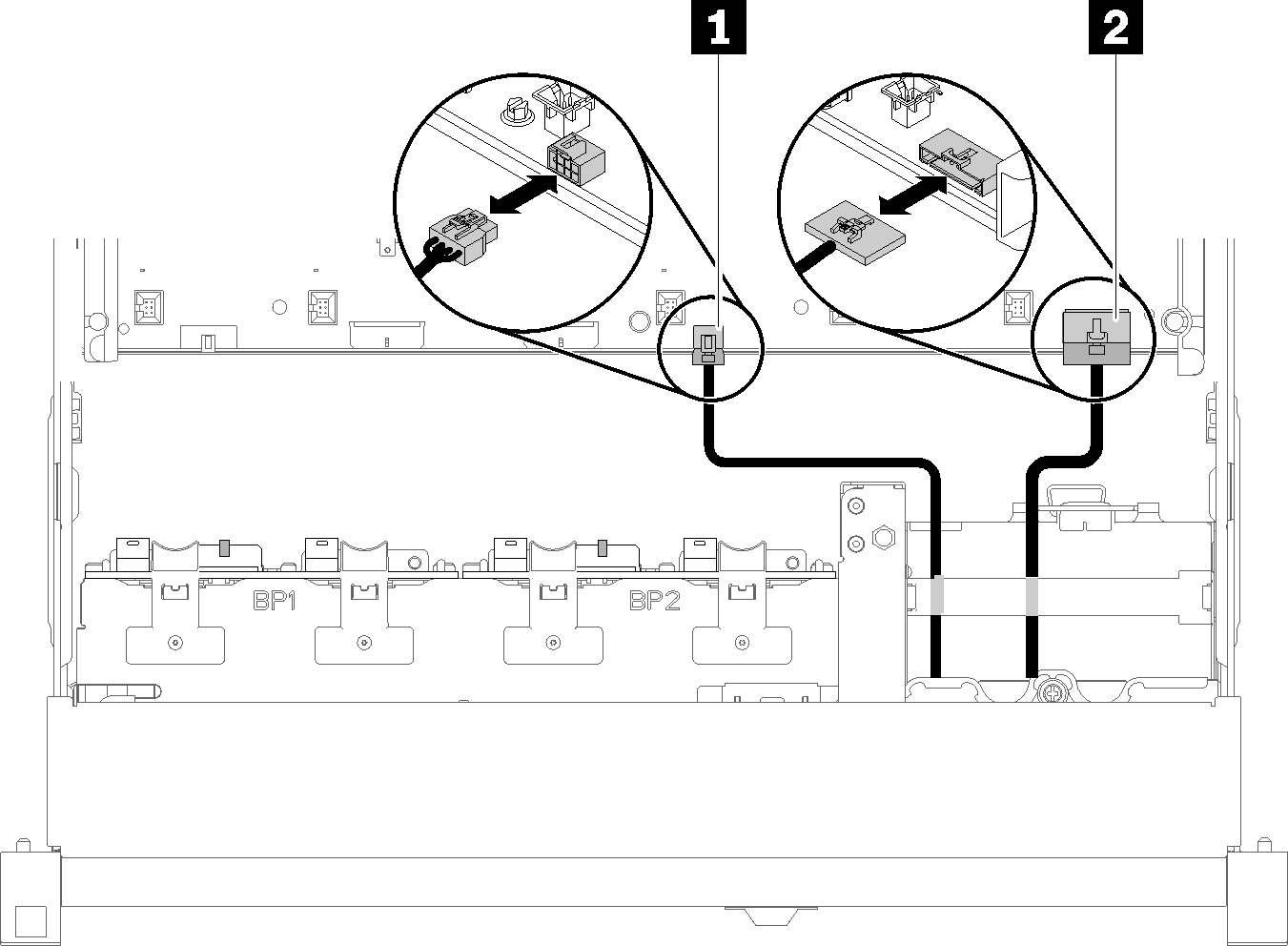
Table 1. USB 2.0 cable and front operator panel cable 1 USB 2.0 cable 2 Front operator panel cable NoteMake sure the USB 3.0 connector stays vertical when being removed from the system board.Figure 2. Removing USB 3.0 connector vertically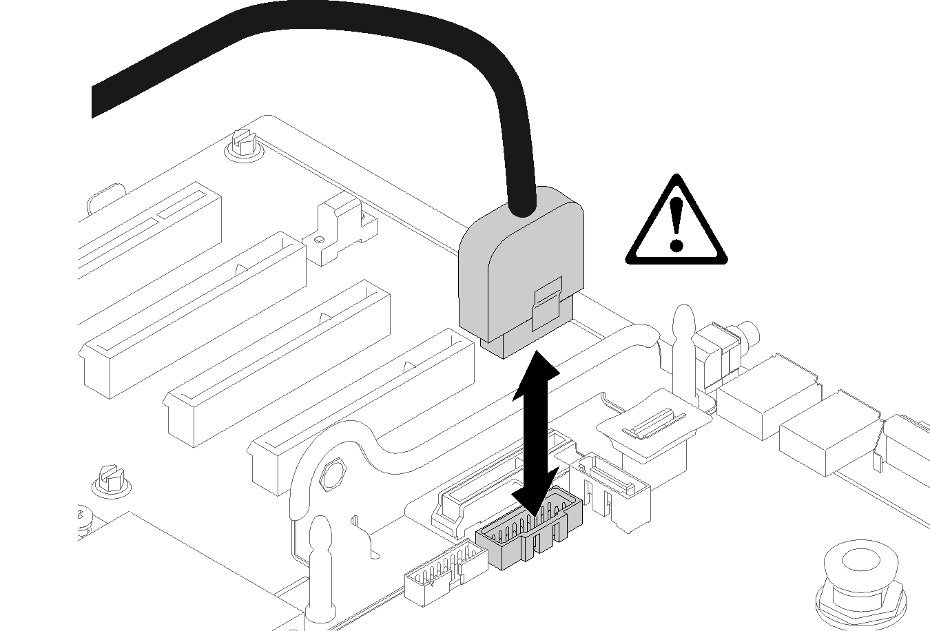
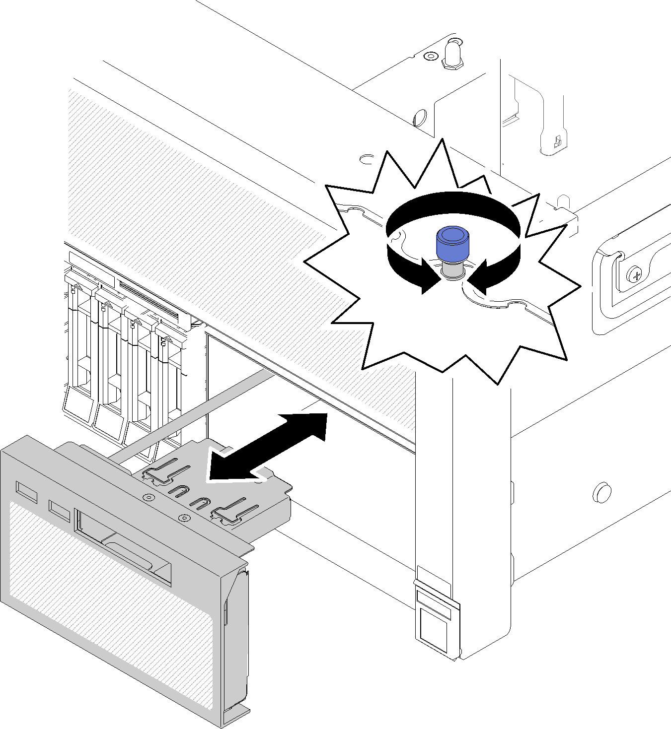
- Push the tray assembly slightly out of the server; then; grasp it from the front and pull it out from the server.Figure 3. Operator panel tray assembly removal
If you are instructed to return the component or optional device, follow all packaging instructions, and use any packaging materials for shipping that are supplied to you.
Demo video