Cabling a dual-interconnect configuration
Procedures for cabling theThinkAgile CP dual-interconnect switch configuration.
Hardware management network connections (dual-interconnect configuration)
Connect the following ports to the management switch:
Primary interconnect port 47 using a SFP+ Direct Attach Cable (DAC)
Compute block port (C.M.) using a RJ45 patch cable
Upper storage block port (S.U.M.) using a RJ45 patch cable
Lower storage block port (S.L.M.) using a RJ45 patch cable
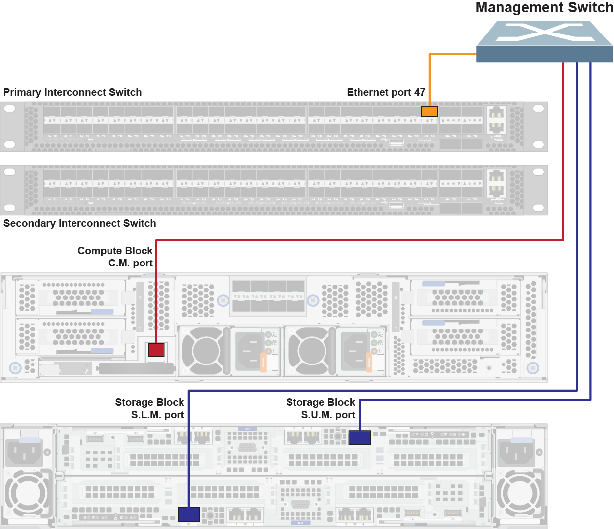
If not using the Lenovo ThinkSystem NE0152T RackSwitch as the management switch, you may require different cables for the management network connections.
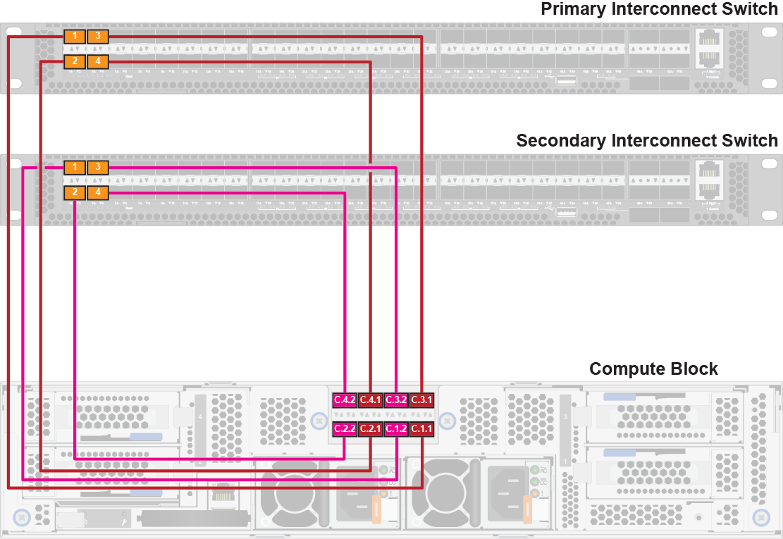
Compute block connections (dual-interconnect configurations)
The compute block consists of an enclosure with up to four compute nodes, which are numbered as follows:

Connect the compute nodes according to the populated compute node location and the corresponding port mapping. The cables to be used are clearly labeled; make sure that you use the correct cables.
You need two SFP+ Direct Attach Cables (DACs) for each populated compute node.
The compute block port mapping is as follows:
Front compute node location | Back network port mapping | Network interconnect port |
|---|---|---|
Top left | Compute node 3, port 1 (C.3.1) | Primary interconnect, port 3 |
Compute node 3, port 2 (C.3.2) | Secondary interconnect, port 3 | |
Top right | Compute node 4, port 1 (C.4.1) | Primary interconnect, port 4 |
Compute node 4, port 2 (C.4.2) | Secondary interconnect, port 4 | |
Bottom left | Compute node 1, port 1 (C.1.1) | Primary interconnect, port 1 |
Compute node 1, port 2 (C.1.2) | Secondary interconnect, port 1 | |
Bottom right | Compute node 2, port 1 (C.2.1) | Primary interconnect, port 2 |
Compute node 2, port 2 (C.2.2) | Secondary interconnect, port 2 |
You only need to cable the number of compute nodes that are installed in the compute enclosure.
Storage block connections (dual-interconnect configurations)
Connect the storage controllers according to the populated controller location and corresponding port mapping and interconnect. The cables to be used are clearly labeled; make sure that you use the correct cables.
You need eight Category 6 patch cables and eight SFP+ transceivers. Attach a single SFP+ transceiver to each patch cable.
The storage block port mapping is as follows:
Front storage controller location | Back network port mapping | Network interconnect port |
|---|---|---|
Upper | Upper storage controller, port 1 (S.U.1) | Primary interconnect, port 17 |
Upper storage controller, port 2 (S.U.2) | Primary interconnect, port 20 | |
Upper storage controller, port 3 (S.U.3) | Secondary interconnect, port 17 | |
Upper storage controller, port 4 (S.U.4) | Secondary interconnect, port 20 | |
Lower | Lower storage controller, port 1 (S.L.1) | Primary interconnect, port 21 |
Lower storage controller, port 2 (S.L.2) | Primary interconnect, port 24 | |
Lower storage controller, port 3 (S.L.3) | Secondary interconnect, port 21 | |
Lower storage controller, port 4 (S.L.4) | Secondary interconnect, port 24 |

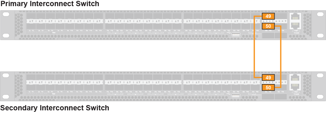
Peer-link connection (dual-interconnect configuration)
Set up the peer link between the interconnects using the QSFP+ Direct Attach Cables (DACs) that are provided with the configuration.
Connect port 49 on the primary interconnect to port 49 on the secondary interconnect.
Connect port 50 on the primary interconnect to port 50 on the secondary interconnect.