System-board switches
Use this information to locate the system-board switches.
The following illustration shows the location of the switch block on the lower system board.
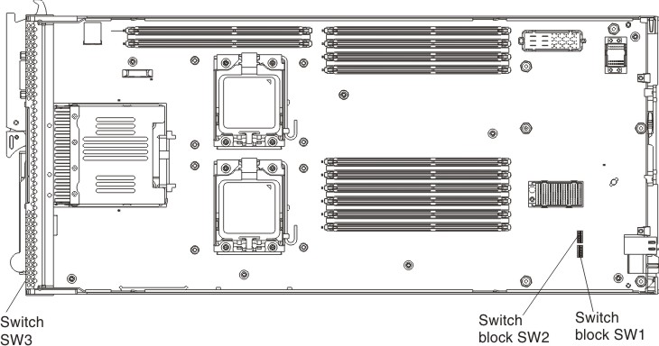
The following table describes the functions of the switches on switch blocks SW1, SW2, and SW3 on the lower system board.
Note
Unless otherwise noted, the default position for all switches, including those that are listed as
Reserved,is Off.
| Switch number | Description | Definition |
|---|---|---|
| SW1-1 | Password override | The default position is Off. Changing this switch to the On position overrides the power-on password. |
| SW1-2 | Real time clock (RTC) reset | The default position is Off. Changing this switch to the On position resets the RTC. A momentary toggle is all that is required. To avoid excessive CMOS battery drain, do not leave this switch in the On position. |
| SW1-3 | Reserved. | Reserved. |
| SW1-4 | Force IMM2 update | The default position is Off. Changing this switch to the On position bypasses the operational firmware image and performs a IMM2 firmware update, if the normal firmware update procedure results in an inoperative IMM2. Note Use this jumper only if the normal firmware update procedure fails and the operational firmware image is corrupted. Use of this jumper disables normal IMM2 operation. |
| SW1-5 | Boot backup UEFI | The default position is Off. Changing this switch to the On position forces the compute node to boot from the backup UEFI image. |
| SW1-6 | Reserved. | Reserved. |
| SW1-7 | Reserved. | Reserved. |
| SW1-8 | Reserved. | Reserved. |
| SW2-1 | Reserved. | Reserved. |
| SW2-2 | Reserved. | Reserved. |
| SW2-3 | Reserved. | Reserved |
| SW2-4 | Trusted Platform Module (TPM) physical presence | The default position is Off. Changing this switch to the On position indicates physical presence to the TPM. |
| SW2-5 | IMM2 TPM physical presence | The default position is Off. Changing this switch to the On position indicates physical presence of the IMM2 to the TPM. |
| SW2-6 | Reserved. | Reserved. |
| SW2-7 | Reserved. | Reserved. |
| SW2-8 | Boot backup IMM2 | When the switch is in the default Off position, the compute node will boot by using the primary IMM2 firmware image. When the switch is in the On position, the compute node will boot by using the recovery IMM2 image. Note Use this switch only if the normal firmware update procedure fails and the operational firmware image is corrupted. Use of this switch disables normal baseboard management controller (BMC) operation. |
| SW3 | Force non-maskable interrupt (NMI) | Pressing this recessed button on the front panel of the compute node causes the compute node to stop doing what it is doing. |
The following illustration shows the location of the switch block on the upper system board.
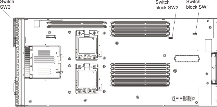
The following table describes the functions of the switches on switch blocks SW1, SW2, and SW3 on the upper system board.
Note
Unless otherwise noted, the default position for all switches, including those that are listed as
Reserved,is Off.
| Switch number | Description | Definition |
|---|---|---|
| SW1-1 | Password override | The default position is Off. Changing this switch to the On position overrides the power-on password. |
| SW1-2 | Real time clock (RTC) reset | The default position is Off. Changing this switch to the On position resets the RTC. A momentary toggle is all that is required. To avoid excessive CMOS battery drain, do not leave this switch in the On position. |
| SW1-3 | Reserved. | Reserved. |
| SW1-4 | Force IMM2 update | The default position is Off. Changing this switch to the On position bypasses the operational firmware image and performs a IMM2 firmware update, if the normal firmware update procedure results in an inoperative IMM2. Note Use this jumper only if the normal firmware update procedure fails and the operational firmware image is corrupted. Use of this jumper disables normal IMM2 operation. |
| SW1-5 | Boot backup UEFI | The default position is Off. Changing this switch to the On position forces the compute node to boot from the backup UEFI image. |
| SW1-6 | Reserved. | Reserved. |
| SW1-7 | Reserved. | Reserved. |
| SW1-8 | Reserved. | Reserved. |
| SW2-1 | Reserved. | Reserved. |
| SW2-2 | Reserved. | Reserved. |
| SW2-3 | Reserved. | Reserved. |
| SW2-4 | Trusted Platform Module (TPM) physical presence | The default position is Off. Changing this switch to the On position indicates physical presence to the TPM. |
| SW2-5 | IMM2 TPM physical presence | The default position is Off. Changing this switch to the On position indicates physical presence of the IMM2 to the TPM. |
| SW2-6 | Reserved. | Reserved. |
| SW2-7 | Reserved. | Reserved. |
| SW2-8 | Boot backup IMM2 | When the switch is in the default Off position, the compute node will boot by using the primary IMM2 firmware image. When the switch is in the On position, the compute node will boot by using the recovery IMM2 image. Note Use this switch only if the normal firmware update procedure fails and the operational firmware image is corrupted. Use of this switch disables normal baseboard management controller (BMC) operation. |
| SW3 | Force non-maskable interrupt (NMI) | Pressing this recessed button on the front panel of the compute node causes the compute node to stop doing what it is doing. |
Give documentation feedback