
System-board switches and jumpers

The following illustration shows the location and description of the switches and jumpers.

Note
The connectors on the system board illustrations might vary slightly from your system board, depending on your server model.
Figure 1. Location and description of switches and jumpers
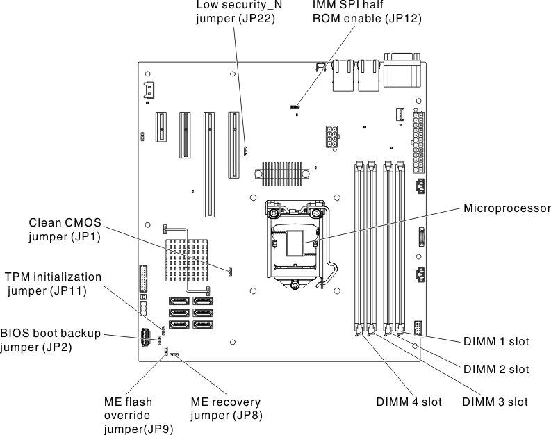
Location and description of switches and jumpers
Table 1. System board jumpers.
Jumper numberJumper nameJumper setting
JP1Clear CMOS jumper
  • Pins 1 and 2: Keep CMOS data (default).
  • Pins 2 and 3: Clear CMOS data.
JP2BIOS boot backup (boot block jumper)
  • Pins 1 and 2: Boot from primary BIOS page (default).
  • Pins 2 and 3: Boot from backup BIOS page.
JP10TPM physical presence jumper
  • Pins 1 and 2: Normal (default).
  • Pins 2 and 3: Pull down TPM.
JP11TPM initialization jumper
  • Pins 1 and 2: Normal (default).
  • Pins 2 and 3: Initiate TPM.
JP12IMM recovery jumper
  • Pins 1 and 2: Loads the secondary (backup) IMM firmware ROM page.
  • Pins 2 and 3: Normal (default) Loads the primary IMM firmware ROM page.
JP22Low security N jumper
  • Pins 1 and 2: Normal (default).
  • Pins 2 and 3: Activate low security.
Note
  1. If no jumper is present, the server responds as if the pins are set to 1 and 2.
  2. Changing the position of the boot block jumper from pins 1 and 2 to pins 2 and 3 before the server is turned on alters which flash ROM page is loaded. Do not change the jumper pin position after the server is turned on. This can cause an unpredictable problem.
  3. If a message is shown indicating that your Trusted Platform Module's (TPM) physical presence is asserted, it is an indication that the system is vulnerable to potential security risks. This occurs when the jumper setting of JP11 is at Pins 2 and 3. Switching the jumper setting to Pins 1 and 2 of JP11 will deassert the Trusted Platform Module's (TPM) physical presence.
Important
  1. Before you change any switch settings or move any jumpers, turn off the server. Review the information in Safety, Installation guidelines, Handling static-sensitive devices, and Turning off the server.
  2. Any system-board switch or jumper block that is not shown in the illustrations in this document are reserved.