4-drive-capable model
The following illustrations show the cabling information for the model of 4x2.5-inch hot-swap drive bays.
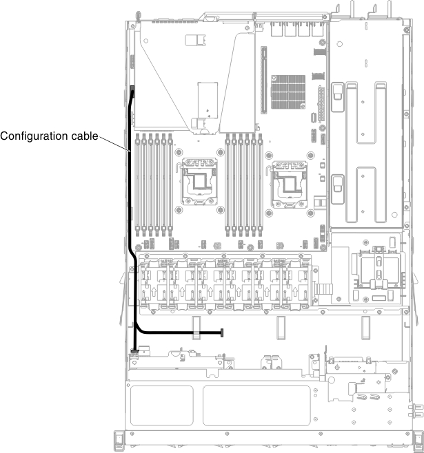
The following illustration shows the cabling information for the configuration cable in the server:
Figure 1. Cabling information for the configuration cable
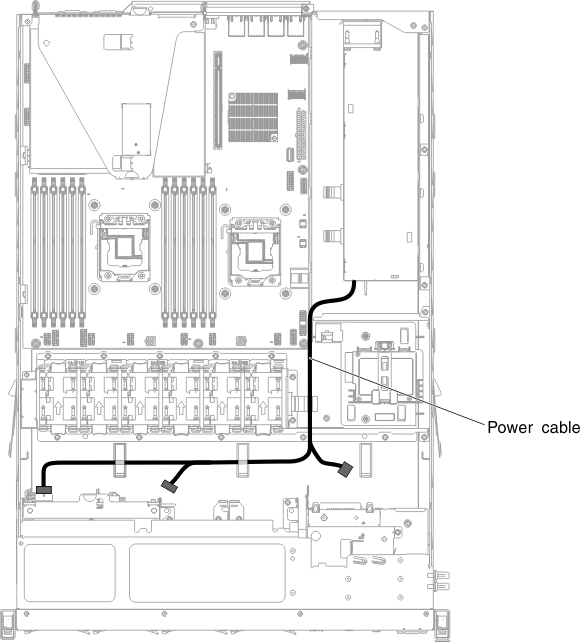
The following illustration shows the cabling information for the power cable in the server:
Figure 2. Cabling information for the power cable (redundant power model)
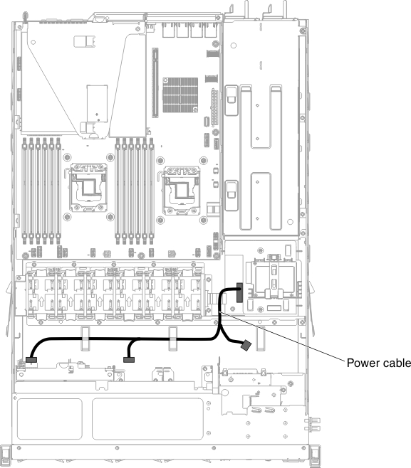
Figure 3. Cabling information for the power cable (fixed power model)
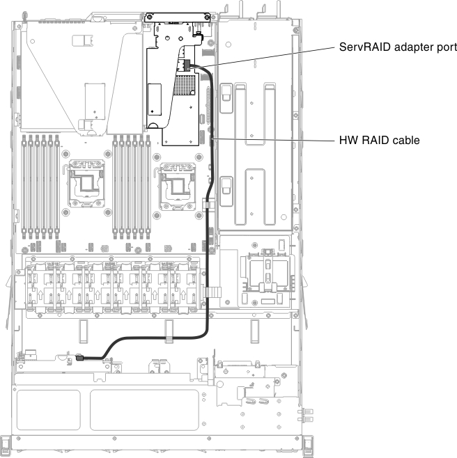
The following illustration shows the cabling information for the hardware RAID cable in the server:
Figure 4. Cabling information for the hardware RAID cable
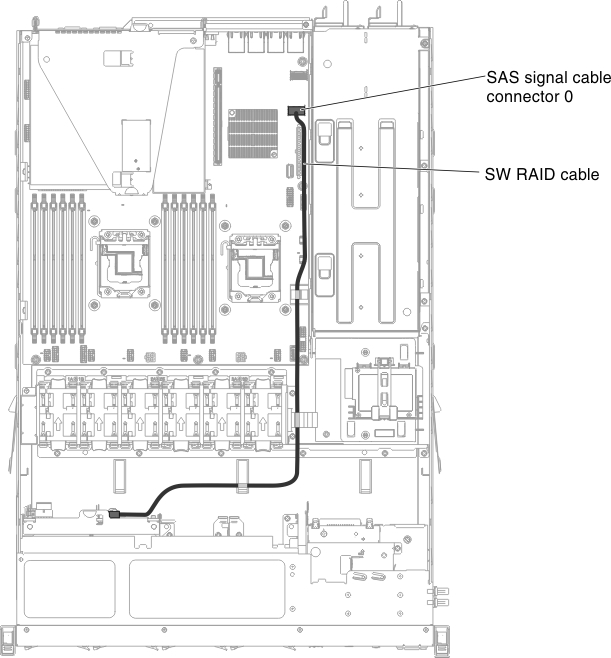
The following illustration shows the cabling information for the software RAID cable in the server:
Figure 5. Cabling information for the software RAID cable
Give documentation feedback