Rear view
The following illustration shows the connectors on the rear of the server.
The server configuration may be of the following three:
Figure 1. Rear view connector illustration when three low-profile PCI riser card assemblies are installed.
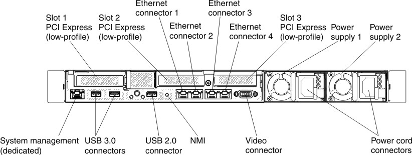
Figure 2. Rear view connector illustration when two additional rear 2.5-inch hot-swap hard disk drives installed in server. The PCI riser card assembly for this server configuration is low-profile.
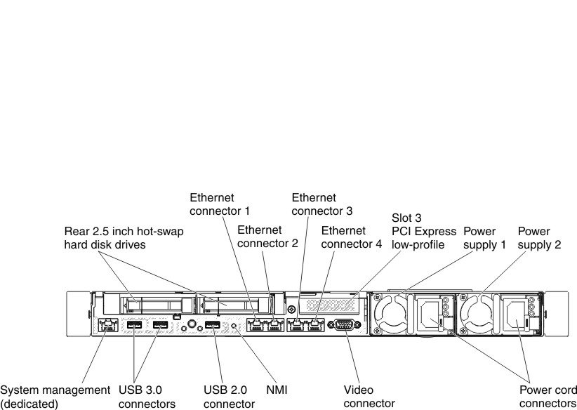
Figure 3. Rear view connector illustration when one ML2, one full-height half length and one low-profile PCI riser card assembly is installed in the server.
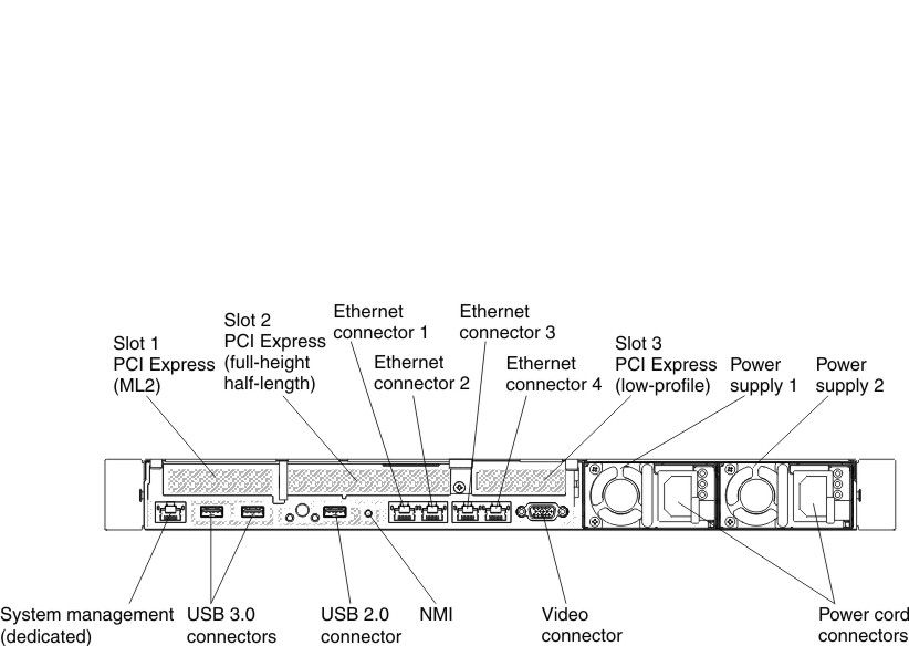
- PCI slot 1: Depending on the server configuration, insert a low-profile PCI Express or an ML2 adapter into this slot.
- PCI slot 2: Depending on the server configuration, insert a half-length, full-height PCI Express or a low-profile PCI Express adapter into this slot.
- PCI slot 3: Insert a low-profile PCI Express into this slot.
- Ethernet connectors: Use either of these connectors to connect the server to a network.
- Systems-management Ethernet connector: Use this connector to connect the server to a network for full systems-management information control. This connector is used only by the integrated management module (IMM2.1). A dedicated management network provides additional security by physically separating the management network traffic from the production network. In shared mode, depending on the network environment, the IMM might disconnect from the network for a short time when the server restarts. You can use the Setup utility to configure the server to use a dedicated systems management network or a shared network.
- USB connectors: Connect a USB device, such as a USB mouse or keyboard to any of these connectors.
- NMI button: Press this button to force a nonmaskable interrupt to the microprocessor. It allows you to blue screen the server and take a memory dump (use this button only when directed by the Lenovo service support). You might have to use a pen or the end of a straightened paper clip to press the button. The NMI button is in the lower left-hand corner on the rear of the server.
- Video connector: Connect a monitor to this connector. The video connectors on the front and rear of the server can be used simultaneously.NoteThe maximum video resolution is 1600 x 1200 at 75 Hz.
- Power cord connector: Connect the power cord to this connector.NotePower supply 1 is the default/primary power supply. If power supply 1 fails, you must replace it immediately.
The following illustration shows the LEDs on the rear of the server.
Figure 4. Rear view LEDs
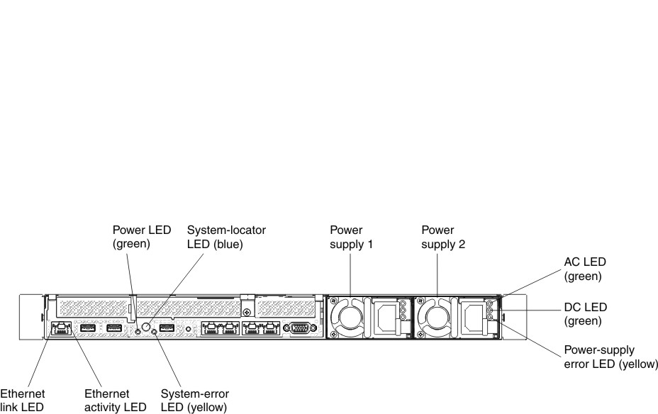
- Ethernet link LEDs: When these LEDs are lit, they indicate that there is an active link connection on the 10BASE-T, 100BASE-TX, or 1000BASE-TX interface for the Ethernet port.
- Ethernet activity LEDs: When these LEDs are lit, they indicate that the server is transmitting to or receiving signals from the Ethernet LAN that is connected to the Ethernet port.
- Power-on LED: When this LED is lit and not flashing, it indicates that the server is turned on. The states of the power-on LED are as follows:
- Off: Power is not present, or the power supply or the LED itself has failed.
- Flashing rapidly (4 times per second): The server is turned off and is not ready to be turned on. The power-control button is disabled. This will last approximately 5 to 10 seconds.
- Flashing slowly (once per second): The server is turned off and is ready to be turned on. You can press the power-control button to turn on the server.
- Lit: The server is turned on.
- System-locator LED: Use this LED to visually locate the server among other servers. You can use Systems Director or IMM2.1 Web interface to light this LED remotely.
- System-error LED: When this LED is lit, it indicates that a system error has occurred. An LED on the operator information panel is also lit to help isolate the error.
- DC power LED: Each hot-swap ac power supply has a dc power LED. When the dc power LED is lit, it indicates that the power supply is supplying adequate dc power to the system. During typical operation, both the ac and dc power LEDs are lit. For any other combination of LEDs, see ac power-supply LEDs.
- AC power LED: Each hot-swap ac power supply has an ac power LED. When the ac power LED is lit, it indicates that sufficient power is coming into the power supply through the power cord. During typical operation, the ac power LED is lit. For any other combination of LEDs, see ac power-supply LEDs.
- Power-supply error LED: When the power-supply error LED is lit, it indicates that the power supply has failed.NotePower supply 1 is the default/primary power supply. If power supply 1 fails, you must replace the power supply immediately.
Give documentation feedback