Front view
The following illustrations show the controls, LEDs, and connectors on the front of your server model.
Note
* in the following illustrations indicates optional hardware components.
2.5-inch hard disk drive server model.
- 8 hard-disk drive configuration / 16 hard-disk drive configuration front viewFigure 1. 8 hard-disk drive configuration / 16 hard-disk drive configuration 1
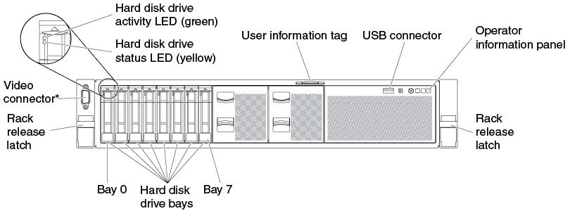 Figure 2. 8 hard-disk drive configuration / 16 hard-disk drive configuration 2: with USB connectors and optical drive
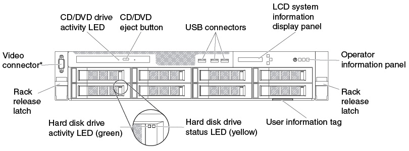
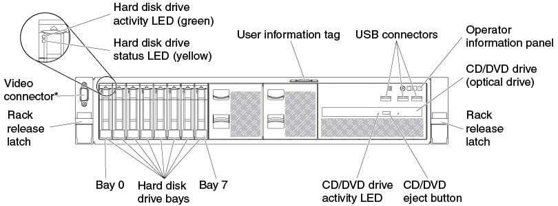 Figure 3. 8 hard-disk drive configuration / 16 hard-disk drive configuration 3: with LCD system information display panel, USB connectors, and optical drive
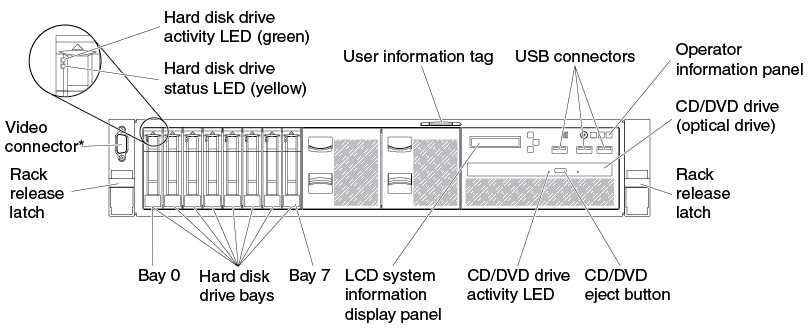
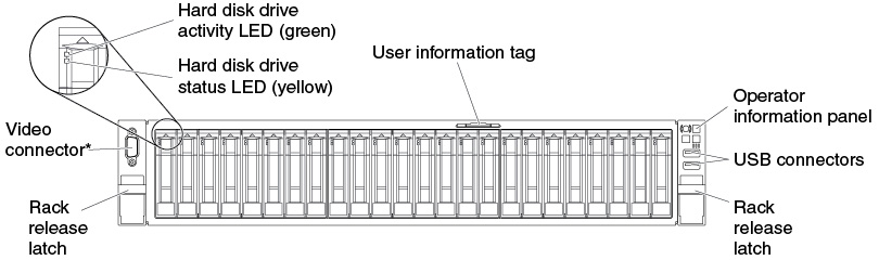
- 24 hard-disk drive configuration front viewFigure 4. 24 hard-disk drive configuration front view
3.5-inch hard disk drive server model.
- 8 hard-disk drive configuration front viewFigure 5. 8 hard-disk drive configuration front view
- 12 hard-disk drive configuration front viewFigure 6. 12 hard-disk drive configuration front view
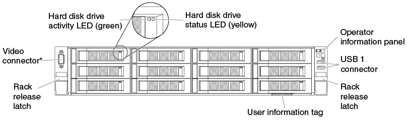
- Rack release latches: Press the latches on each front side of the server to slide the server out from the rack enclosure.
Hard disk drive activity LEDs: These green LEDs are on all hot swap drives.
When this LED is flashing, it indicates that the drive is actively reading or writing data.
For SAS and SATA drives, this LED is off when the drive is powered but not active.
For NVMe (PCIe SSD) solid state drives, this LED is on solid when the drive is powered but not active.
- Hard disk drive status LEDs: This LED is used on hot-swap SAS or SATA hard disk drives. When this LED is lit, it indicates that the drive has failed. If an optional ServeRAID controller is installed in the server, when this LED is flashing slowly (one flash per second), it indicates that the drive is being rebuilt. When the LED is flashing rapidly (three flashes per second), it indicates that the controller is identifying the drive.
- Optional DVD eject button: Press this button to release a DVD or CD from the optional DVD drive.
- Optional DVD drive activity LED: When this LED is lit, it indicates that the optional DVD drive is in use.
- Operator information panel: This panel contains controls and LEDs that provide information about the status of the server. For information about the controls and LEDs on the operator information panel, see Operator information panel.
- Video connector: Connect a monitor to this connector. The video connectors on the front (optional) and rear of the server can be used simultaneously.NoteThe maximum video resolution is 1600 x 1200 at 75 Hz.
- USB connectors: Connect a USB device, such as a USB mouse or keyboard to any of these connectors.
Give documentation feedback