Rear view
This section contains information about the LEDs and connectors on the rear of the server.
The following illustrations show the connectors and LEDs on the rear of the server.
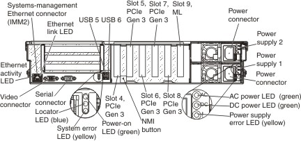
- Systems-management Ethernet connector: Use this connector to manage the server, by using a dedicated management network. If you use this connector, the Integrated management module II (IMM2) cannot be accessed directly from the production network. A dedicated management network provides additional security by physically separating the management network traffic from the production network. You can use the Setup utility to configure the server to use a dedicated systems-management network or a shared network.
- Video connector: Connect a monitor to this connector. The video connectors on the front and rear of the server can be used simultaneously.NoteThe maximum video resolution is 1600 x 1200 at 75 Hz.
- Serial connector: Connect a 9-pin serial device to this connector. The serial port is shared with the IMM2. The IMM2 can take control of the shared serial port to redirect serial traffic, using Serial over LAN (SOL).
- Ethernet activity LEDs: When these LEDs are lit, they indicate that the server is transmitting to or receiving signals from the Ethernet LAN that is connected to the Ethernet port.
- Ethernet link LEDs: When these LEDs are lit, they indicate that there is an active link connection on the 100BASE-TX, 1000BASE-TX, or 10GBASE-TX interface for the Ethernet port.
- Locator LED: Use this LED to visually locate the server among other servers. You can use Systems Director to light this LED remotely. The IMM2 can also be used to turn this LED on and off. This LED is functionally equivalent to the locator LED on the front of the server.
- System-error LED: When this LED is lit, it indicates that a system error has occurred. An LED on the light path diagnostics panel is also lit to help isolate the error. This LED is functionally equivalent to the system-error LED on the front of the server.
- Power-on LED: When this LED is lit and not flashing, it indicates that the server is turned on. This LED is functionally equivalent to the power-on LED on the front of the server. The states of the power-on LED are as follows:
- Off: Input power is not present, or the power supply or the LED itself has failed.
- Flashing rapidly (3 times per second): The server is turned off and is not ready to be turned on. The power-on button is disabled. This lasts approximately 10 seconds after input power has been applied or restored.
- Flashing slowly (once per second): The server is turned off and is ready to be turned on. You can press the power-on button to turn on the server.
- Lit: The server is turned on.
- USB connectors: Connect a USB device, such as a USB mouse, keyboard, or other device, to any of these connectors.
- NMI button: Press this button to force a nonmaskable interrupt to the microprocessor. You might have to use a pen or the end of a straightened paper clip to press the button. You can also use it to force a blue-screen memory dump. Use this button only when you are directed to do so by Lenovo Support.
- ML adapter slot: Insert a quad-port GbE, dual-port 10 Gbase-T, or dual-port 10 GbE SFP+ ML2 adapter into this slot. (see System-board internal connectors for the location of the ML adapter slot on the system board. and Installing an adapter for information about the installation of the ML2 adapters.
- PCIe adapter slots: Insert the PCIe adapters into these slots (see System-board internal connectors for the locations of the PCIe adapter slots on the system board). See Table 1 and Installing an adapter for information about adapters.
- Power-supply connector: Connect the power cord to this connector.
- AC power LED: Each hot-swap power supply has an ac power LED and a dc power LED. When the ac power LED is lit, it indicates that sufficient power is being supplied to the power supply through the power cord. During normal operation, both the ac and dc power LEDs are lit. For any other combination of LEDs, see Power-supply LEDs.
- DC power LED: Each hot-swap power supply has a dc power LED and an ac power LED. When the dc power LED is lit, it indicates that the power supply is supplying adequate dc power to the system. During normal operation, both the ac and dc power LEDs are lit. For any other combination of LEDs, see Power-supply LEDs.
- Power-supply error LED: When the power-supply error LED is lit, it indicates that the power supply has failed, see Power-supply LEDs.
Give documentation feedback