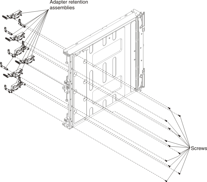
Removing the adapter-retention assembly
Use this information to remove the adapter-retention assembly.
Before you remove the adapter-retention assembly, complete the following steps:
- Read Safety and Installation guidelines.
- If the compute node is installed in a Flex System chassis, remove it (see Removing a compute node from a chassis for instructions).
- Carefully lay the compute node on a flat, static-protective surface, orienting the compute node with the bezel pointing toward you.
The adapter-retention assembly consists of five separate parts. You can replace only the parts that you choose and save the unused parts for future use.
To remove the adapter-retention assembly, complete the following steps.

- Remove the cover (see Removing the compute node cover).
- Remove the air baffles.
- If necessary, remove the I/O expansion adapters (see Removing an I/O expansion adapter).
- Carefully place the chassis on its side with the front handle side up.
- Using a T9 Torx screwdriver, remove the three screws that secure the adapter-retention assembly.
- Lift the adapter-retention assembly from the system board.
- Carefully return the chassis to the bottom-side-down orientation.
If you are instructed to return the adapter-retention assembly, follow all packaging instructions, and use any packaging materials for shipping that are supplied to you.
Give documentation feedback