System-board switches
Use this information to locate the system-board switches.
The following illustration shows the location of the switch block on the system board.
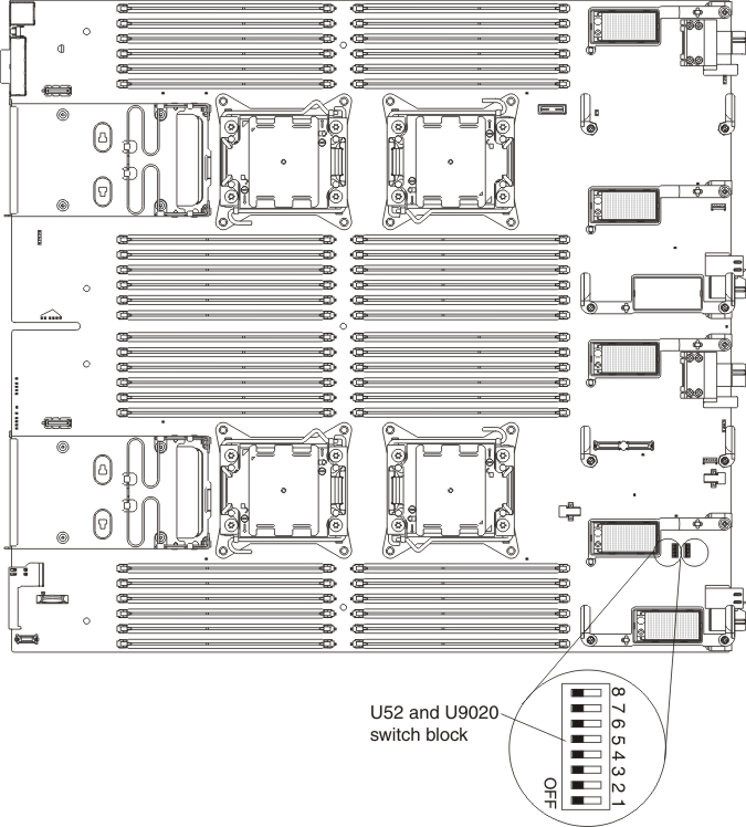
The following table describes the functions of the switches on switch block SW3.
| Switch number | Description | Switch setting | Definition |
|---|---|---|---|
| U52-1 | Password override | The default position Open. | Changing this switch to the Closed position overrides the power-on password. |
| U52-2 | Trusted Platform Module (TPM) physical presence | The default position is Open. | Changing this switch to the Closed position indicates a physical presence to the TPM. |
| U52-3 | Real time clock (RTC) reset | The default position is Open. | Changing this switch to the Closed position resets the RTC. A momentary toggle is all that is required. To avoid excessive CMOS battery drain, do not leave this switch in the Closed position. |
| U52-4 | Boot backup IMM2 | The default position is Open. | When the switch is in the default Open position, the compute node will boot by using the primary IMM2 firmware. When the switch is in the Closed position, the compute node will boot by using a backup of the IMM2 firmware. |
| U52-5 | Boot backup UEFI | The default position is Open. | Changing this switch to the Closed position forces the compute node to boot from the backup UEFI image. |
| U52-6 | IMM force update | The default position is Open. | Changing this switch to the Closed position bypasses the operational firmware image and performs a IMM firmware update, if the normal firmware update procedure results in an inoperative IMM. Note Use this jumper only if the normal firmware update procedure fails and the operational firmware image is corrupted. Use of this jumper disables normal baseboard management controller operation. |
| U52-7 | Wake on LAN (WOL) disable | The default position is Open. | Changing this switch to the Closed position disables WOL. |
| U52-8 | Real time management module (RTMM) flash bypass | The default position is Open. | Changing this switch to the Closed position forces the compute node to use RTMM ROM instead of flash. |
| U9020-1 | Asynchronous reset to configuration logic of FPGA | The default position is Open. | Changing this switch to the Closed position resets FPGA Configuration Logic |
| U9020-2 | Power permission | The default position is Open. | Changing this switch to the closed position enables WOL and the front panel button. |
| U9020-3 | FPGA mux enable | The default position is Open. | Changing this switch to the closed position to enable the FPGA MUX keyboard controls |
| U9020-4 | Future use only | ||
| U9020-5, U9020-6 | Selecting dongle serial port MUX (U9812) | Closed, Closed Open, Closed Closed, Open Open, Open | BE3-1 TX/RXRTMM TX/RXIMM TX/RX SIO TX/RX |
| U9020-7, U9020-8 | Selecting dongle serial port MUX (U9811) | Closed, Closed Open, Closed Closed, Open Open, Open | BE3-2 TX/RX FPGA TX/RX IMM TX/RX SIO RTS/CTS |
Give documentation feedback