Rear view LEDs
The rear of the system provides system LEDs.
Figure 1. Rear view LEDs – type 1
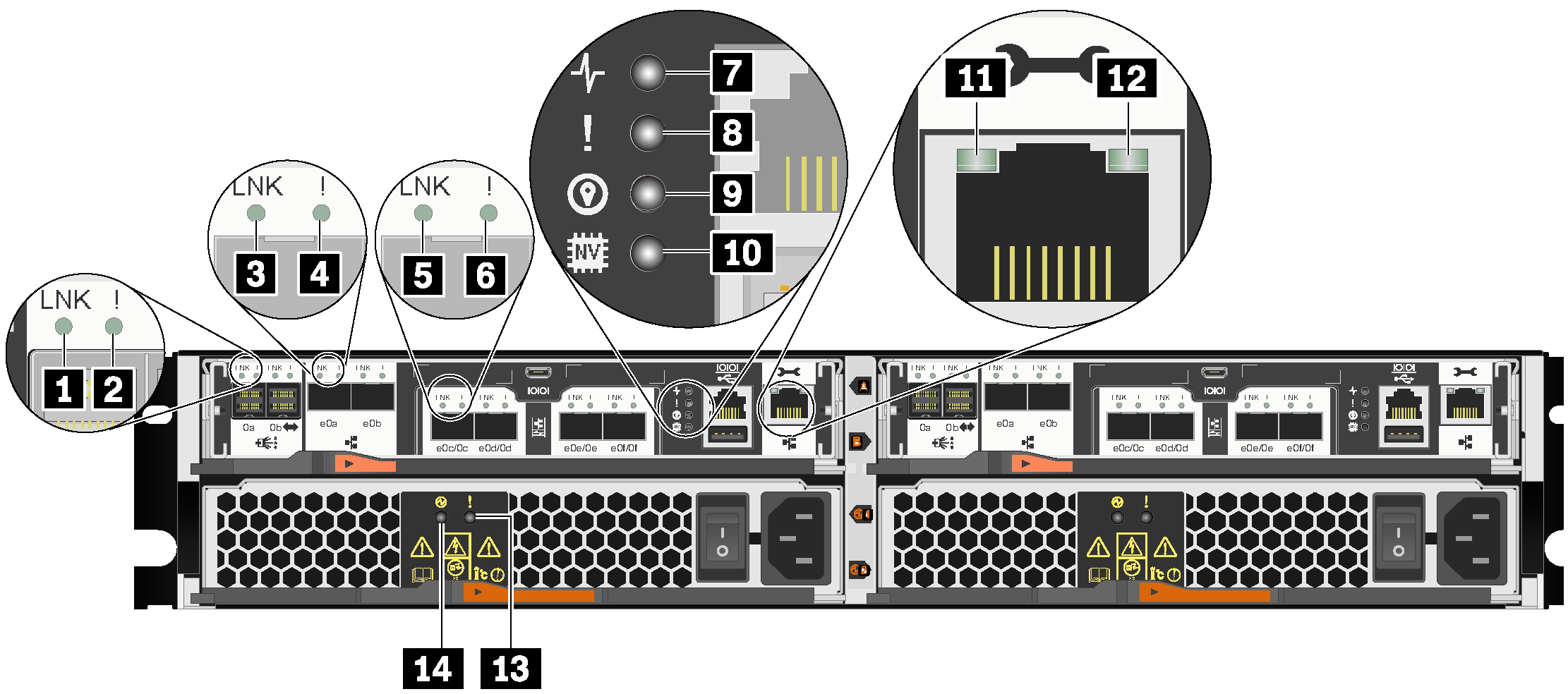
| 1 MiniSAS HD port link LED (4) | 2 MiniSAS HD port attention LED (4) |
| 3 SFP+ Ethernet port link LED (4) | 4 SFP+ Ethernet port attention LED (4) |
| 5 UTA2 SFP+ port link LED (8) | 6 UTA2 SFP+ port attention LED (8) |
| 7 Controller activity LED (2) | 8 Controller attention LED (2) |
| 9 Controller location LED (2) | 10 NVRAM LED |
| 11 RJ45 management port link LED (2) | 12 RJ45 management port activity LED (2) |
| 13 Power supply attention LED (2) | 14 AC power good LED (2) |
Figure 2. Rear view LEDs – type 2
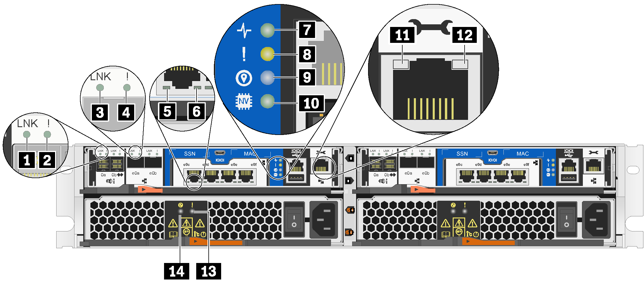
| 1 MiniSAS HD port link LED (4) | 2 MiniSAS HD port attention LED (4) |
| 3 SFP+ Ethernet port link LED (4) | 4 SFP+ Ethernet port attention LED (4) |
| 5 RJ45 10 GbE host port link LED (8) | 6 RJ45 10 GbE host port activity LED (8) |
| 7 Controller activity LED (2) | 8 Controller attention LED (2) |
| 9 Controller location LED (2) | 10 NVRAM LED |
| 11 RJ45 management port link LED (2) | 12 RJ45 management port activity LED (2) |
| 13 Power supply attention LED (2) | 14 AC power good LED (2) |
1 2 MiniSAS HD port LEDs
Each MiniSAS HD port has two status LEDs.
| Status LED | Color | Status | Description |
|---|---|---|---|
| 1 MiniSAS HD port link LED | Green | On | Link is established on at least one external SAS lane. |
| None | Off | No link is established on any external SAS lane | |
| 2 MiniSAS HD port attention LED | Yellow | On | SAS link requires attention. |
| None | Off | SAS link operates normally. |
3 4 SFP+ Ethernet port LEDs
Each SFP+ Ethernet port has two status LEDs.
| Status LED | Color | Status | Description |
|---|---|---|---|
| 3 SFP+ Ethernet port link LED | Green | On | A connection is established on the port. |
| None | Off | No connection is established on the port. | |
| 4 SFP+ Ethernet port attention LED | Amber | On | The port requires attention. |
| None | Off | The port operates normally. |
5 6 Type 1 – UTA2 SFP+ port LEDs
Each UTA2 SFP+ port has two status LEDs.
| Status LED | Color | Status | Description |
|---|---|---|---|
| 5 UTA2 SFP+ port link LED | Green | On | A connection is established on the port. |
| None | Off | No connection is established on the port. | |
| 6 UTA2 SFP+ port attention LED | Amber | On | The port requires attention. |
| None | Off | The port operates normally. |
5 6 Type 2 – RJ45 10 GbE host port LEDs
Each RJ45 10 GbE host port has two status LEDs.
| Status LED | Color | Status | Description |
|---|---|---|---|
| 5 RJ45 10 GbE host port link LED | Green | On | A link is established between the port and some upstream device. |
| None | Off | No link is established. | |
| 6 RJ45 10 GbE host port activity LED | Amber | Blinking | Traffic is flowing over the connection. |
| None | Off | No traffic is flowing over the connection. |
7 Controller activity LED
| Status | Color | Description |
|---|---|---|
| On | Green | The controller is active. |
| Off | None | The controller is off. |
8 Controller attention LED
| Status | Color | Description |
|---|---|---|
| On | Yellow | The controller requires attention. |
| Off | None | The controller operates normally. |
9 Controller location LED
| Status | Color | Description |
|---|---|---|
| On or blinking | Blue | The controller location LED is manually activated to help locating the controller. |
| Off | None | The controller location LED is not activated. |
10 NVRAM LED
| Status | Color | Description |
|---|---|---|
| Blinking | Green | IO is being written to local flash memory. |
| On | Green | Data is in cache and has not been written to local disks. |
| Off | None | No data is in cache that needs to be written to local disks. |
11 12 RJ45 management port LEDs
Each RJ45 management port has two status LEDs.
| Status LED | Color | Status | Description |
|---|---|---|---|
| 11 RJ45 management port link LED | Green | On | A link is established between the port and some upstream device. |
| None | Off | No link is established. | |
| 12 RJ45 management port activity LED | Amber | Blinking | Traffic is flowing over the connection. |
| None | Off | No traffic is flowing over the connection. |
13 Power supply attention LED
| Status | Color | Description |
|---|---|---|
| On | Amber | No AC power is present or power supply is failed. |
| Off | None | AC power is present. |
14 AC power good LED
| Status | Color | Description |
|---|---|---|
| On | Green | AC power is present and good. |
| Off | None | AC power is not detected. |
Give documentation feedback